A Builder’s Journal
Notes and photographs of building a 5.28m one-hatch baidarka
by Courtney Starks of Bellingham, Washington
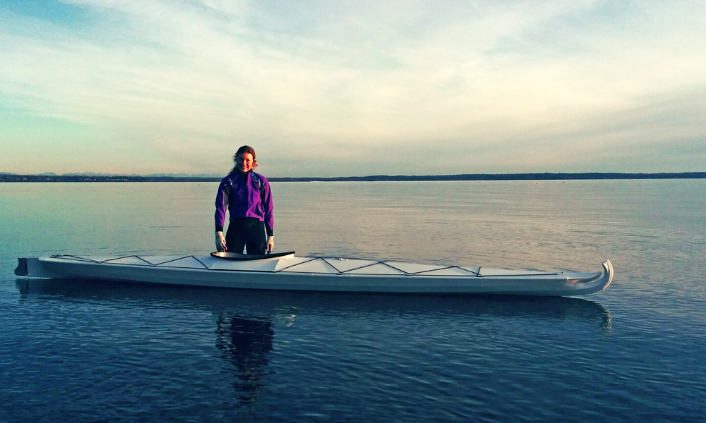
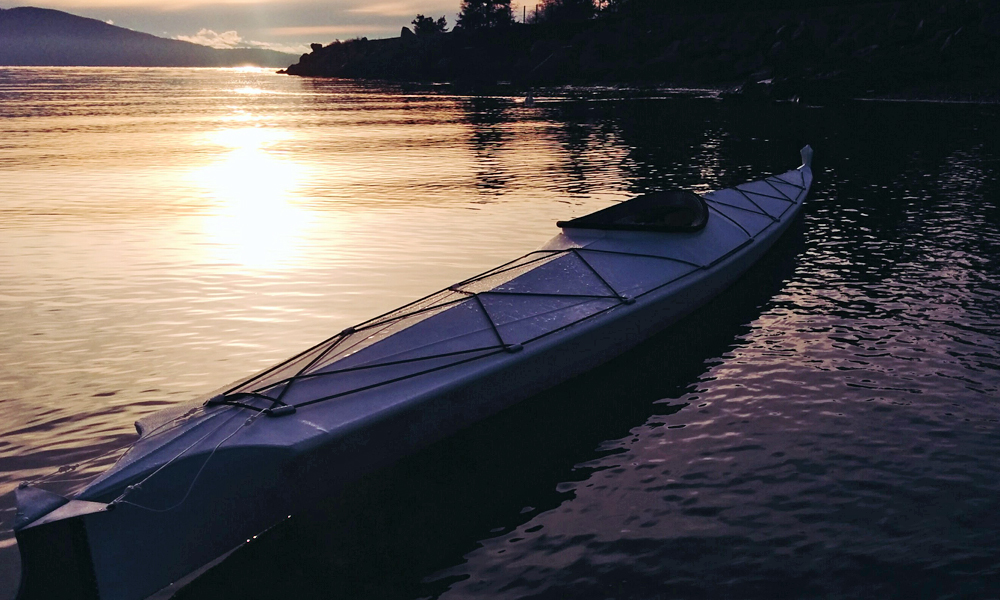
Virgo, my baidarka
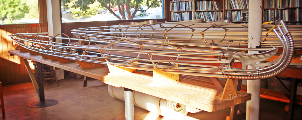
At rest on a peaceful lake, or joyously bounding through the ruffled waves of the sea, boats seem to yearn for adventure and freedom. No two are exactly similar - each will possess its own character. I have always been drawn to boats, and years ago I decided that I would build my own. I am fortunate to have met George Dyson, who shares an appreciation for boats and the sea. It is he who designed this beautiful craft, reconstructing the Aleutian baidarka from the dusty pages of the past.
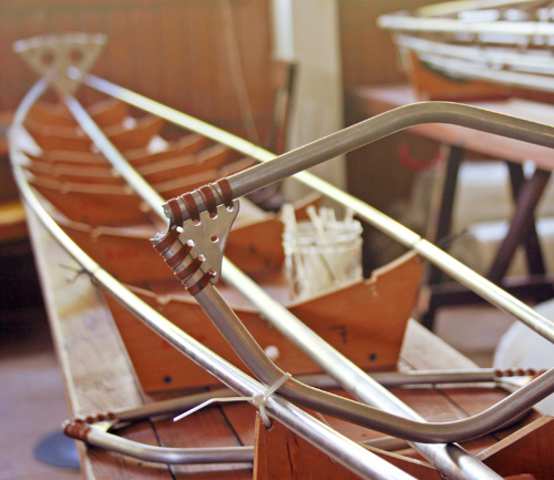
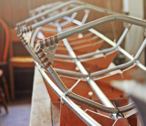
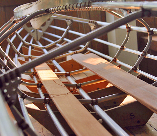
I built my boat in George's tidy workshop near the waterfront, surrounded by boxes of paper charts and the company of a curious cat. People often peered through the wide window facing the street as I worked, admiring the sleek and unusual skeletons of each baidarka. An old fan hummed as I worked over the frame of my boat, carefully lashing the intersection of every stringer with nylon cordage. The long hours passed quietly, yet I was absorbed and appreciated every moment. It is my hope that others who undertake to build this boat may benefit from all that I have learned.
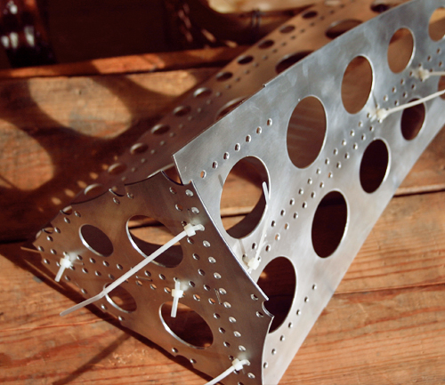
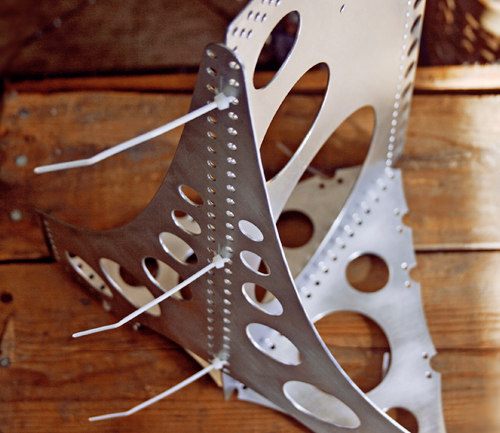
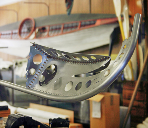
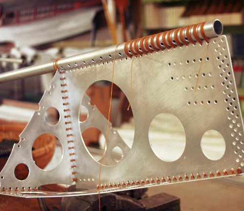
Flatware
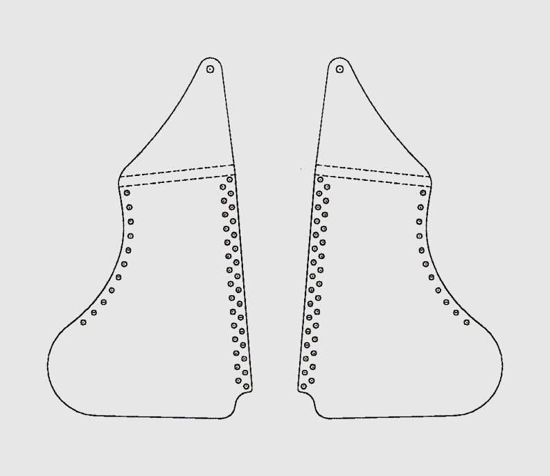
The stem (bow) and stern flatware components, with the gussets for each rib frame provide the rigid structure for the baidarka frame. Each component is cut from sheet aluminum, with the lightening and lashing holes drilled at the proper locations. This process may be done manually using a bandsaw, or more conveniently through a company providing industrial laser cutting.
1/16" sheet aluminum is used for the stern, stem, cockpit coaming, and rudder components. Each rib frame gusset and the stemhead is cut from 1/8" sheet aluminum.
Components
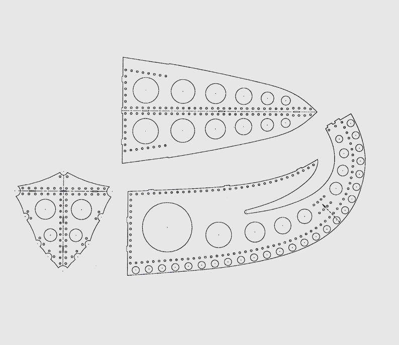
Stem (bow) - bulkhead, foredeck, and stem
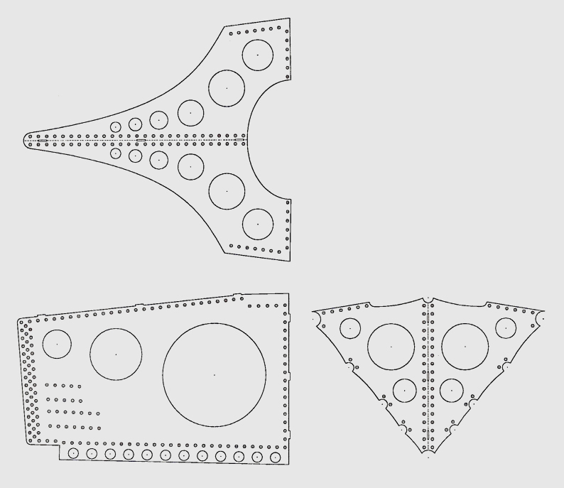
Stern - bulkhead, quarterdeck, and stern
Rudder - port and starboard quadrants
Cockpit coaming
Frame gussets - 5 sets
Stemhead
Countersinking
Each lashing hole must be countersunk to remove the sharp edge that will chafe the nylon cordage. Use a sharp countersinking bit (1/2" to 3/4" diameter) at low RPM, on a drill press or by hand. Bevel each hole edge to approximately 1/3 of the sheet thickness. This must be done to both sides of each lashing hole.
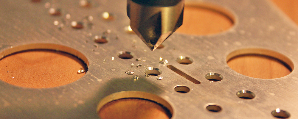
Take care not to bevel deeper than 1/3 of the sheet thickness on either side, as doing so will cause a sharp edge to form at the center of the hole. If this does happen, use a swivel head deburring tool to remove the edge.
Deburring
Both the lightening holes and outer edges of each flatware component are deburred to prevent damage to the fabric skin. Remove the sharp notches using a swivel head deburring tool for curved edges, and a flat file for straight edges. As with the lashing holes, both sides of each edge is deburred.
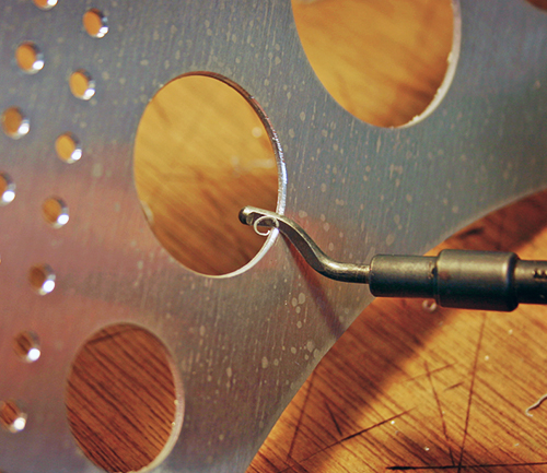
Swivel head deburring tool
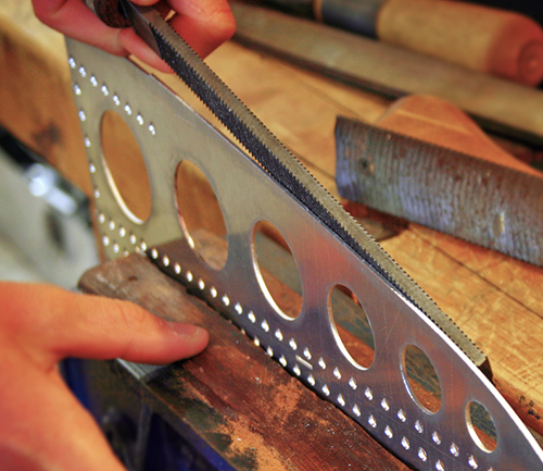
Flat file
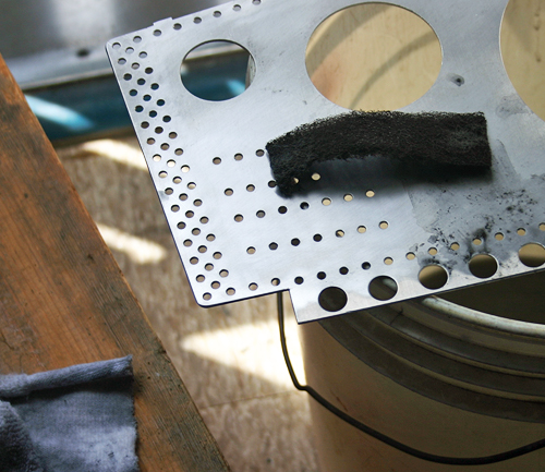
Polishing
After deburring, a polishing wheel is used to smooth the surface and edges of each flatware component. For outer edges, hold the component at an angle to the polishing wheel taking care not to damage the soft material with a sharp corner. Remove sharp notches from the component surface by applying pressure and moving in a circular manner around each hole.
To finish the flatware with a more uniform appearance, scour the surface with an abrasive cleaning pad (Scotch-Brite for example). This is best done with the abrasive pad wet to avoid raising aluminum-oxide dust.
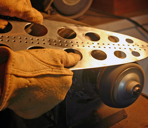
Polishing wheel
Finishing the surface
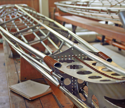
Components
Before the frame of the baidarka takes shape, the stem and stern as well as the rib frames are fabricated.
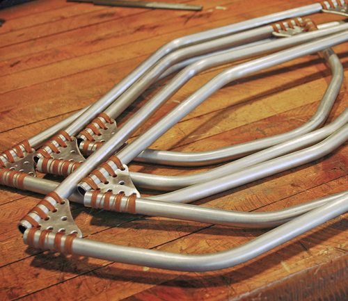
Rib Frames
The frame of the 5.28m baidarka has 8 rib frames, made up of 1/2" diameter aluminum tubing and the frame gussets. At the cockpit, the rib frames have only a hull segment, with all other rib frames also having a deck segment.
| Station | Deck | Hull | Part # | Length |
| 2 | ✓ | 2H | 53.7 cm | |
| ✓ | 2D | 39.7 cm | ||
| 3 | ✓ | 3H | 64.4 cm | |
| ✓ | 3D | 49.7 cm | ||
| 4 | ✓ | 4 | 96.4 cm | |
| 4.5 | ✓ | 4.5 | 94.0 cm | |
| 5 | ✓ | 5 | 114.2 cm | |
| 6 | ✓ | 6H | 66.2 cm | |
| ✓ | 6D | 54.3 cm | ||
| 7 | ✓ | 7H | 57.6 cm | |
| ✓ | 7D | 45.5 cm | ||
| 8 | ✓ | 8H | 44.8 cm | |
| ✓ | 8D | 32.5 cm |
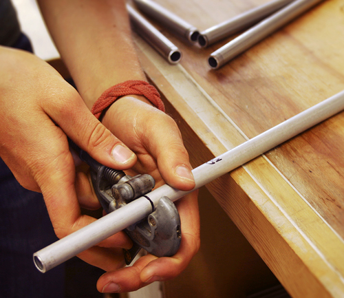
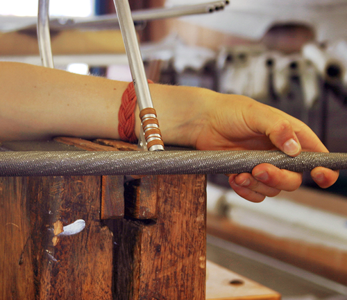
Measuring
Measure a length of tubing for each rib frame section, with an additional 4" (2" on both ends), and cut using a bandsaw or tubing cutter.
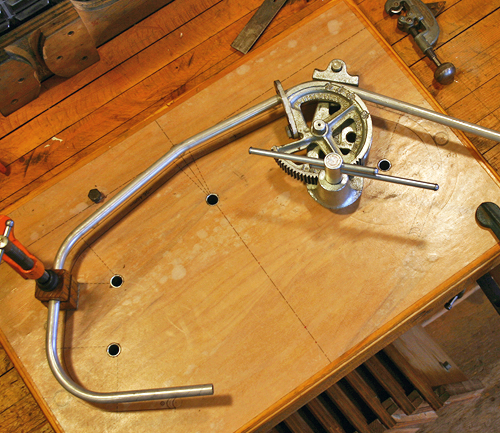
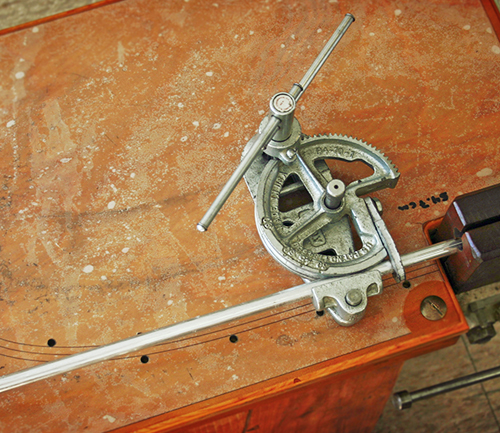
Bending
If using a hand-operated bender, a jig-board may be built (overlayed with a full sized plan for the specific rib frame) with bushings positioned at the center of necessary bending points on which the bender may be situated.
Measure to the center of each tubing section, and mark with a permanent pen. Each deck section has one bend at the center, and the hull sections have three or more. Begin with the center bend on all rib frame sections, applying Vaseline to the tubing as a lubricant. Frequently ensure that each bend is accurate to the full sized plans for the specific rib frame. For hull sections, complete the angles for one side, then reverse to finish in the opposite direction. This will ensure the result is symmetrical.
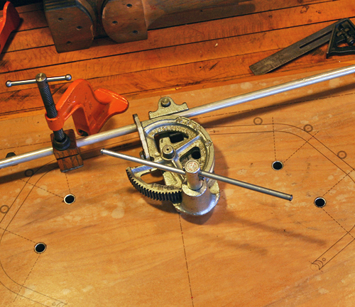
Begin with the center bend
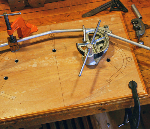
Move to next bend, ensuring alignment
Complete the bend angles for one side
Reverse and finish the opposite side
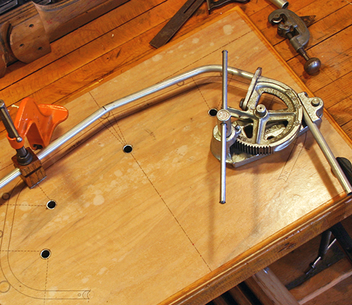
As each rib frame section is completed, clean with acetone and label (with the specific part number). Overlay each rib frame section to its full sized plan, marking the ends on both sides. Use a bandsaw or tubing cutter to remove the additional length, resulting in a tubing section of the proper size.
Again referencing the plans, mark all stringer intersections for each specific rib frame, and label one side of the tubing as forward and the other as aft.
Trim to final length
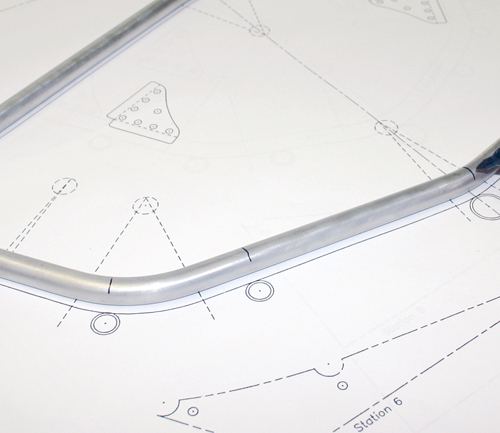
Mark stringer intersections
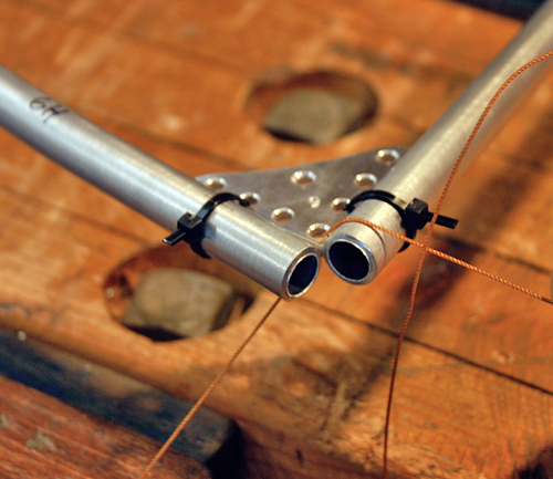
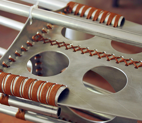
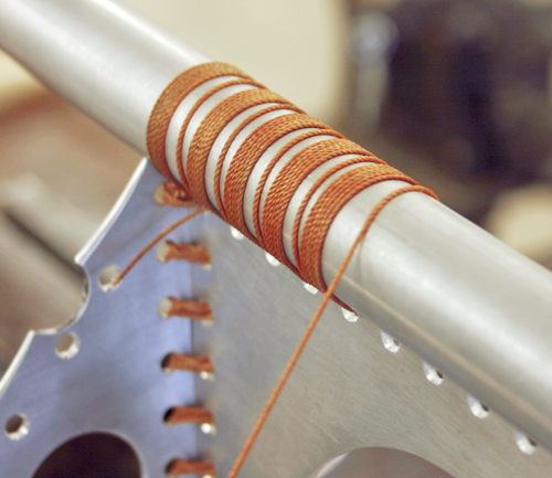
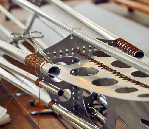
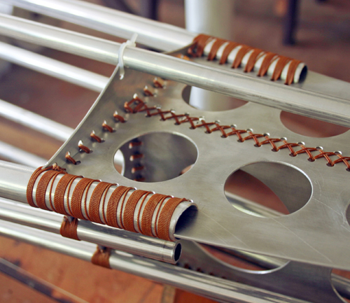
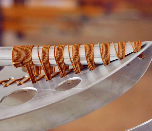
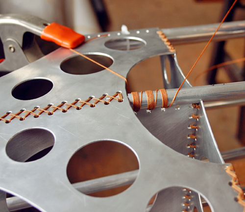
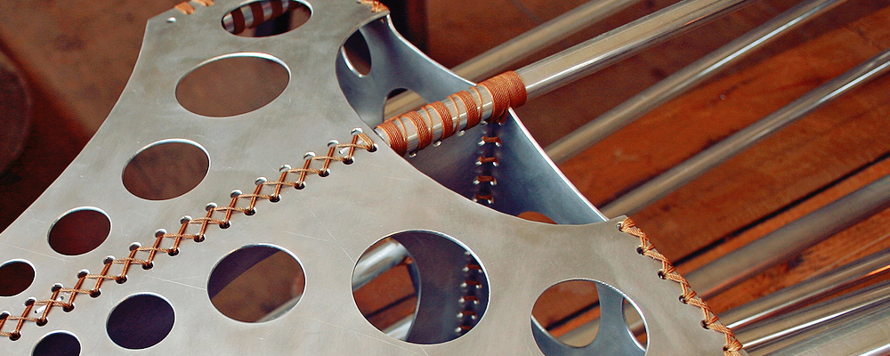
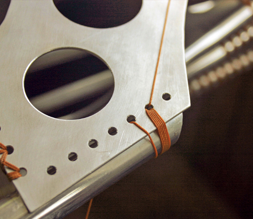
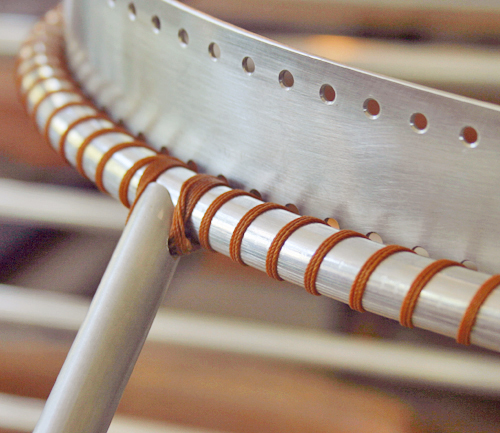
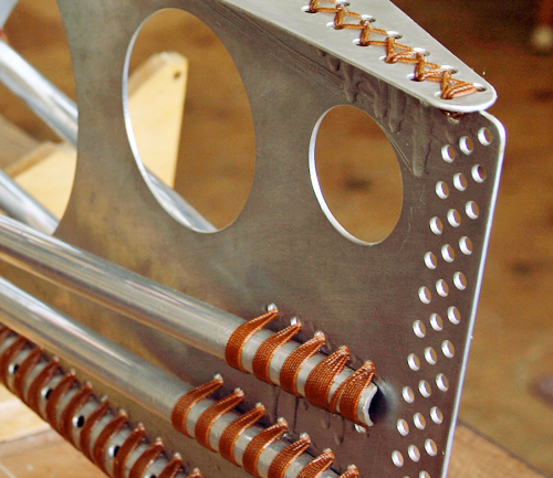
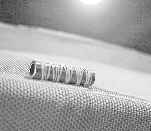
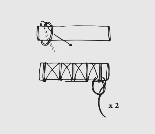
Assembly
- Place the hull and deck section of a rib frame in a vise, aligning the ends and clamping securely.
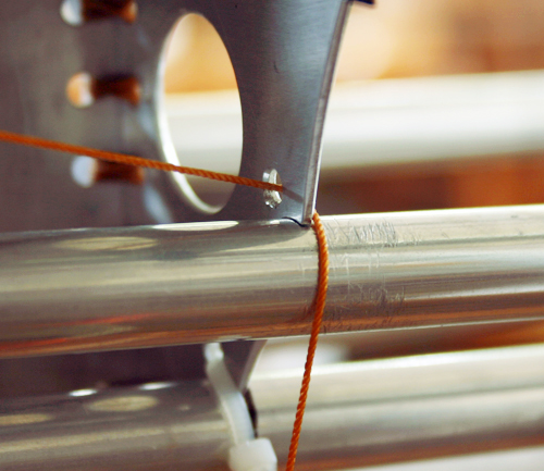
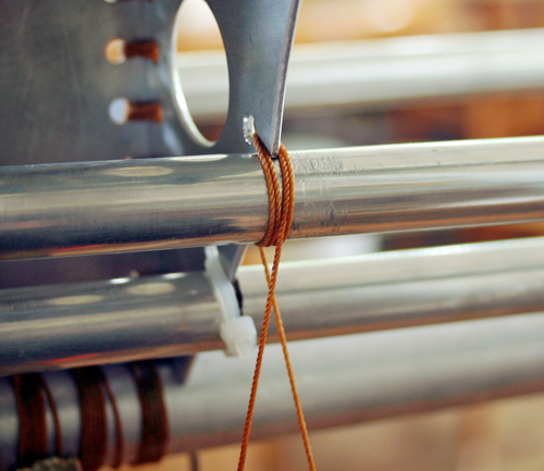
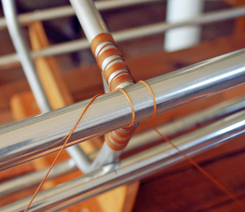
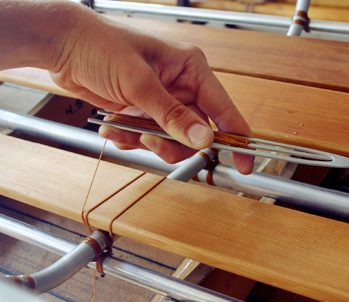
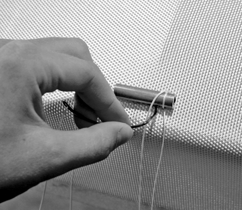
- Cut a length of nylon cordage (3 yards). Position the proper gusset in the angle formed by the rib frame sections (hold in place with a wire or cable tie), and thread the cordage through the outermost (corner) hole. Pull through to the midpoint, and secure one end to your workbench with a spring clamp.
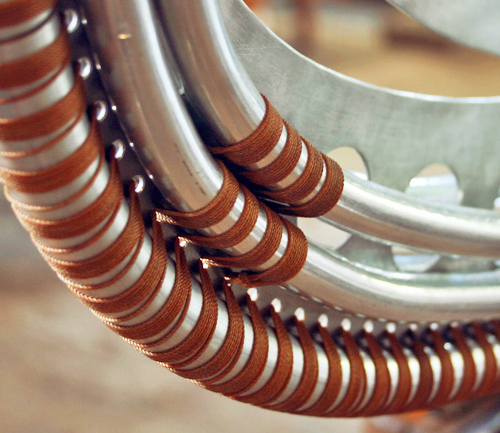
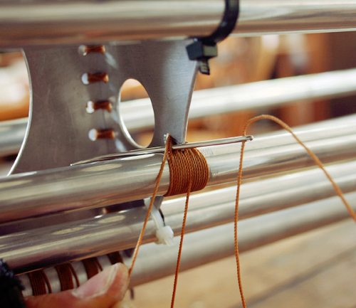
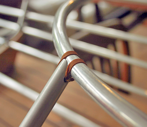
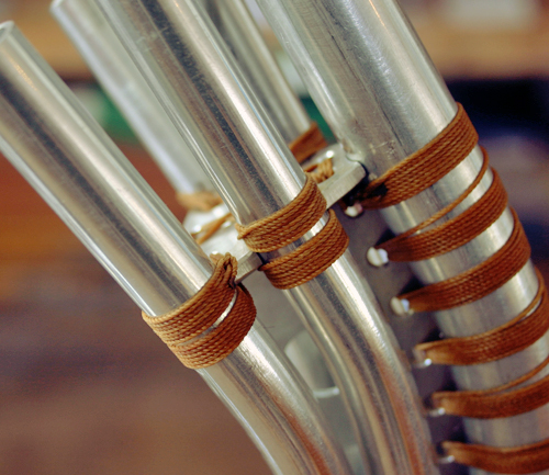
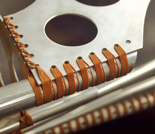
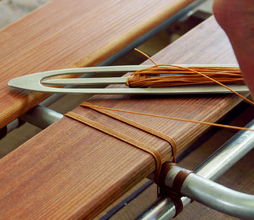
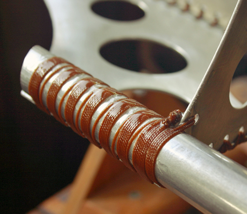
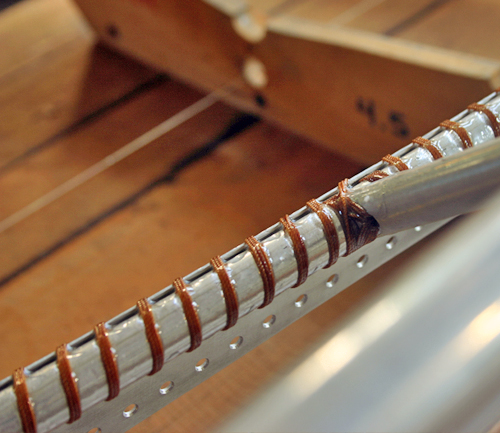
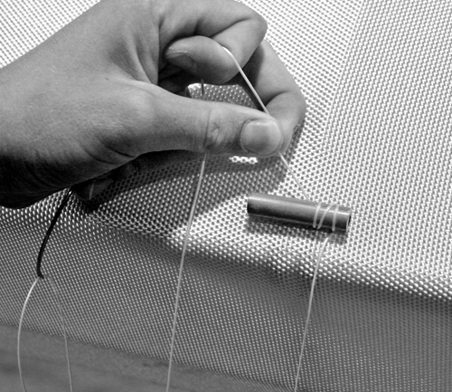
- With the working end, make 6-7 turns through each hole and around the tubing, keeping constant pressure on the cordage. At the end of the row, finish with two half hitches around the group of lashings. Trim and burn end.
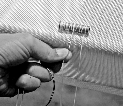
- With the other end of the cordage, repeat step 3 for the opposite row of holes.
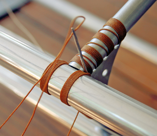
Thread cordage to the midpoint
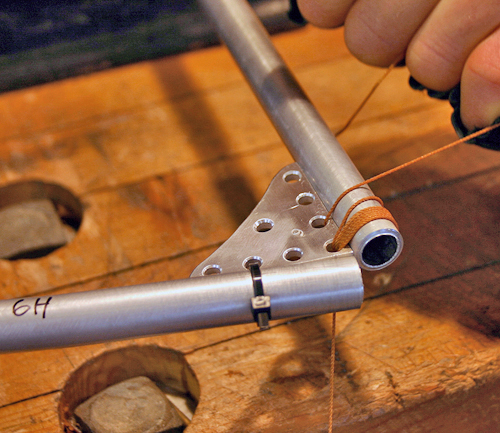
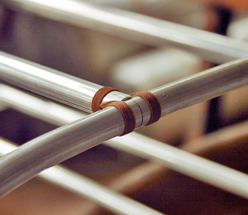
Make 6-7 turns through each hole
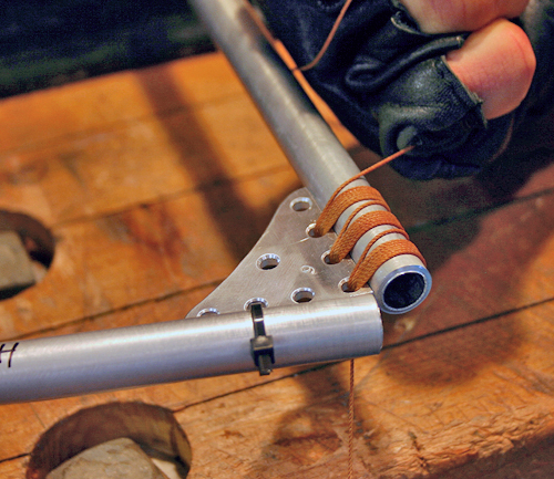
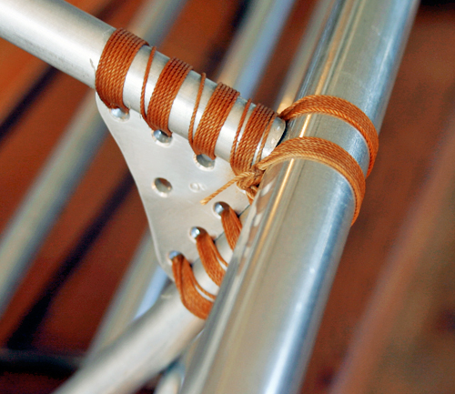
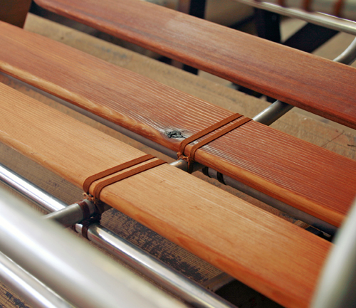
Lash gusset to tubing on one side
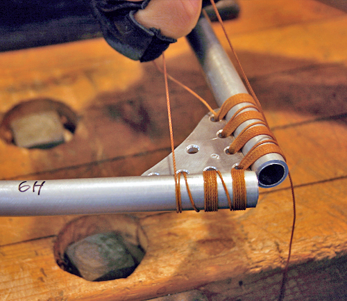
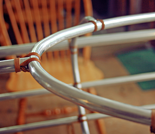
Repeat for the opposite side
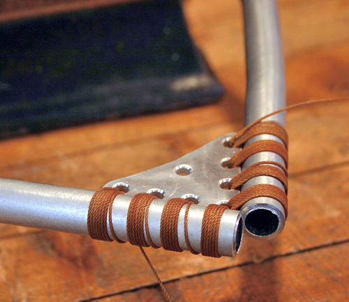
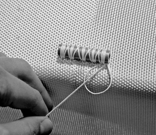
Trim cordage and finish ends with a lighter
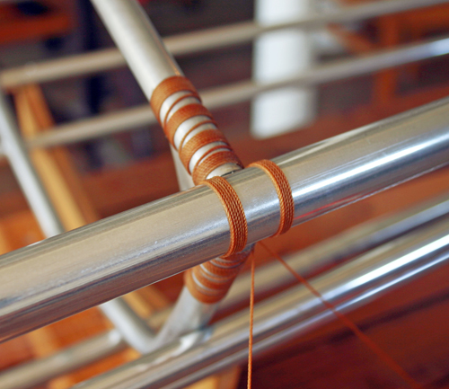
Align gusset to the centerline of the tubing
Bevelling
Each rib frame intersects the gunwale or hatchway at a specific angle. At either end of the frame, the angle is greater, while closer to the center the angle decreases.
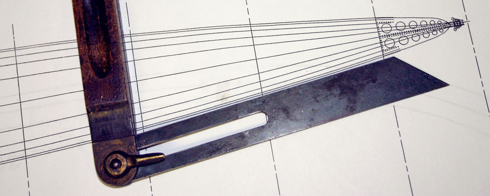
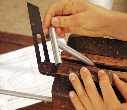
Measure the angle on the inside of the frame
Referencing the plans, measure the angle formed by each rib frame and the gunwale (or hatchway for stations 4, 4.5, and 5) using a T-bevel. If the angle is greater than 90° the bevel is made outwards. Vise versa, the bevel is made inwards for angles less than 90°.
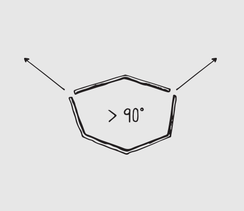
Bevel outwards - stations 2, 3, and 4
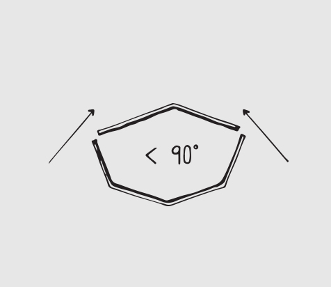
Bevel inwards - stations 5, 6, 7, and 8
Gunwale intersections (stations 2, 3, 6, 7, and 8) are bevelled using a 3/4" rat-tail file. Hatchway intersections (stations 4, 4.5 and 5) are bevelled with a 1/2" rat-tail file.
- Place the rib frame in a vise, with the aft side towards you.
- Select the properly sized rat-tail file, and begin bevelling the determined angle for the specific rib frame - outwards if < 90°, and inwards if > 90°. Frequently verify that the angle is accurate by placing a scrap segment of tubing (3/4" as the gunwale, and 1/2" as the hatchway) at the intersection. Repeat for the other side of the rib frame.
- Finish the tubing ends using a flat file for the outer edge, and a swivel head deburring tool for the inner edge.
Bevel perpendicularly to the vertical rib frame
Verify the angle is correct
On sheet #6 of the full sized plans, a hole is marked on both sides of rib frames 4, 4.5, and 5. Mark the holes on each rib frame, and drill using a 1/8" bit. Countersink holes to remove the rough edges for the hatchway lashings.
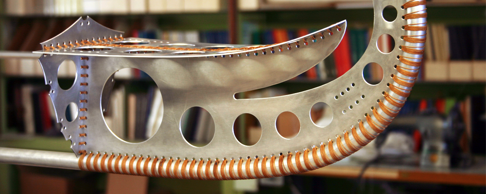
Stem and stern
Pre-assembly
Prior to assembly of the baidarka frame, the flatware components for the stem and stern are permanently lashed.
- Use cable ties or 16-gauge wire to secure the stem bulkhead to the stem. Repeat for the stern components.
- Bend and wire the foredeck to the curved upper edge of the stem.
- Wire the quarterdeck to the stern bulkhead, bending the flatware over the stern.
Pre-assemble stem flatware
Pre-assemble stern flatware
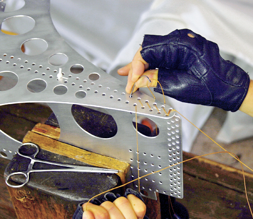
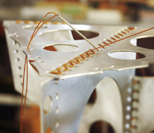
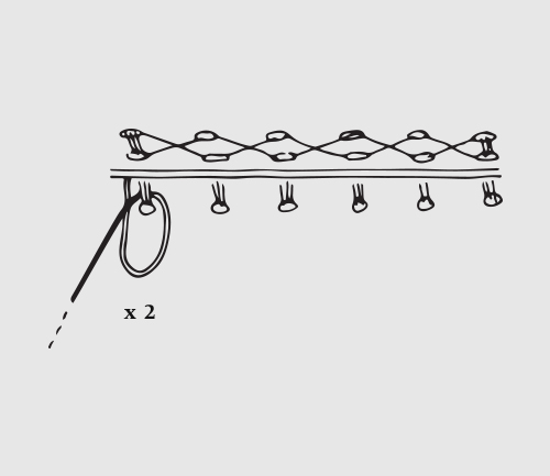
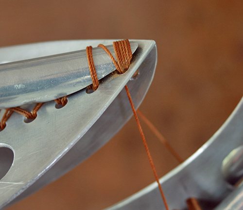
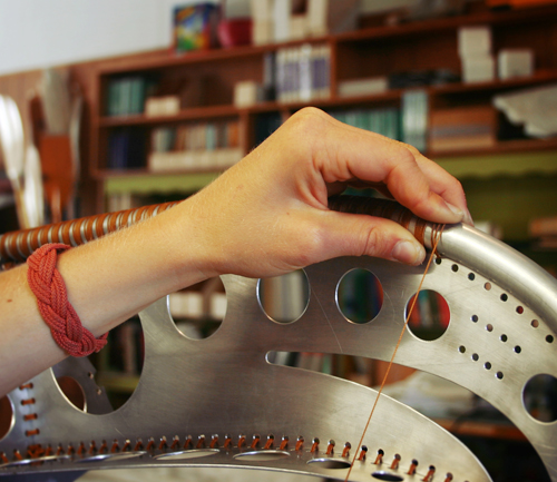
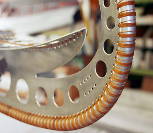
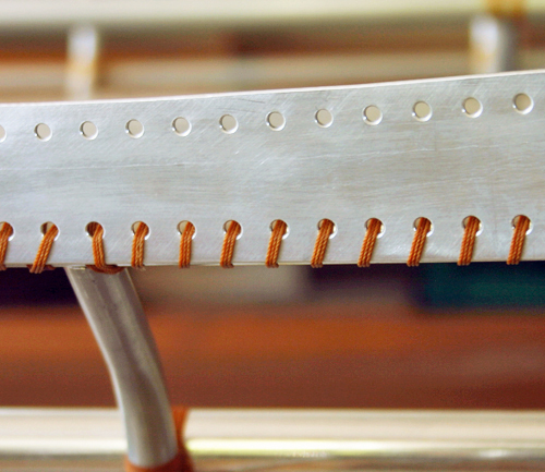
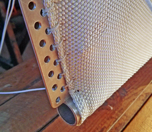
Lashing
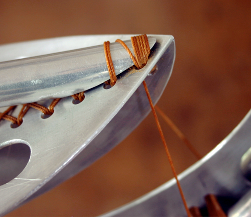
- Place the pre-assembled stem or stern component in a vise and clamp securely. Thread a long, curved needle with a length of cordage (3 arm spans) and securely clamp the other end to the table.
- With the working end, make a few turns through the first two holes on the row and lash forward, crossing over then straight. Remove cable ties or wire as they become unnecessary. Maintain constant pressure when lashing, tensioning away from the hole edge (to prevent chafing).
- At the end of the row, make a few turns to secure the lashings. Return to the beginning of the row, crossing over the first pass of lashings.
- At the first two holes, make a few turns and finish both ends with two half hitches around the lashings. Trim cordage and finish ends with a lighter.
Note: When the cordage becomes to short to continue lashing, trim a new length of cordage (3 arm spans) and attach to the remaining cordage with a sheet bend.
Cross over then straight underneath
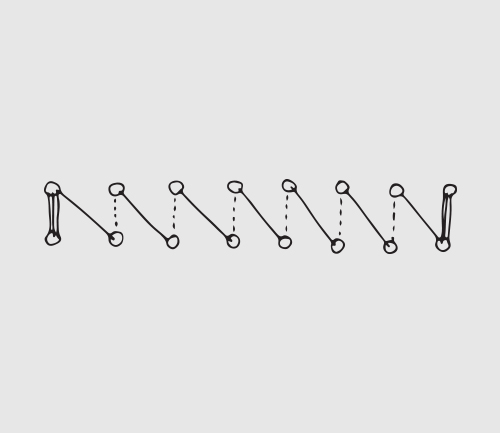
First pass of lashings
Maintain tension on each lashing
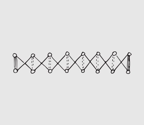
Second pass of lashings
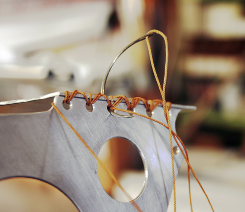
Lashing an edge
Securing the cordage ends
Hatchway
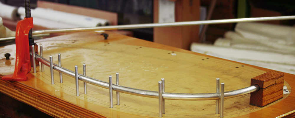
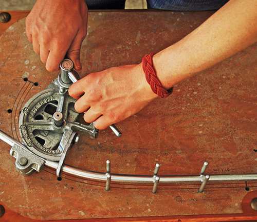
A jig-board may be built overlayed with the full sized hatchway plan, with holes drilled for pins to hold the tubing in position. One half of the hatchway is completed (beginning at the center mark) before finishing in the opposite direction.
Bending
- Measure and cut an 80" section of 1/2" diameter tubing with a bandsaw or tubing cutter. Mark the center with a permanent pen. Apply Vaseline to the tubing, and position bender at the center mark.
- Bend the tubing in small increments (only a few millimeters at a time) to the proper angles, frequently moving the bender away from the curve to compare with the plan. This step ensures each angle is correct, as the tubing has considerable springback. As the hatchway is formed, insert pins to hold the tubing aligned with the plan.
- With one side completed, turn over the tubing and hold the completed side in place with pins. Repeat step 2 to bend the other side of the hatchway.
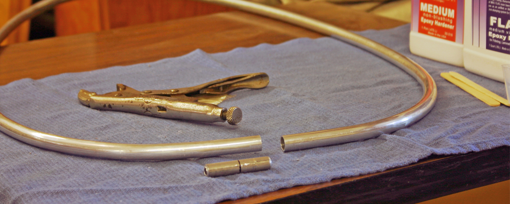
Splicing
- Align the hatchway to the plan and mark the centerline on the overlapped sides. Use a bandsaw to remove the additional length on both ends.
- Roughen the inner surface of each end with a 1/2" bore brush or steel wool, and remove the aluminum dust with acetone.
- Cut a 1 3/4" length of tubing with a diameter equal to the inner diameter of the hatchway tubing. Mark the center with a permanent pen. Use a hacksaw to slot lengthwise for a spring fit.
- Thoroughly apply unthickened epoxy to the inner surfaces of the hatchway tubing ends. Insert the splice sleeve into one side of the hatchway, no further than the center mark. Use locking pliers (Vise-Grips) to firmly clamp the spliced end, and force the remaining part of the sleeve into the other end of the hatchway.
- Clean splice with acetone to remove excess epoxy.
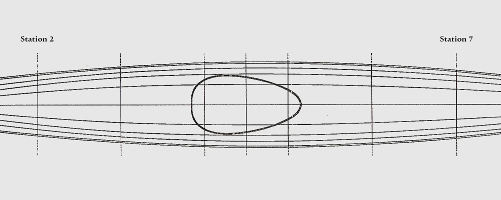
Shaping
Prior to final assembly, the hatchway frame is shaped on its horizontal plane to the camber on the full sized plan.
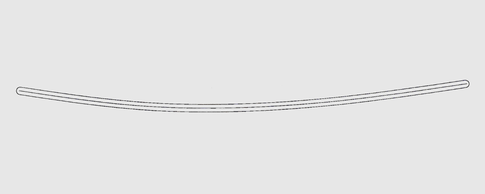
Profile of hatchway frame camber
Stringers
The 5.28m baidarka frame is shaped by 11 longitudinal tubing sections - the keel, deck sections, gunwales, and hull stringers.
| Part # | Type | Diameter | Quantity | Total Length | ||||
| Ø | Keel | 3/4" | 1 |
|
||||
| I | Stringer | 1/2" | 2 |
|
||||
| II | Stringer | 1/2" | 2 |
|
||||
| III | Stringer | 1/2" | 2 |
|
||||
| IV | Gunwale | 3/4" | 2 | 475.0 cm | ||||
| V | Deck (Forward) | 1/2" | 1 |
|
||||
| V | Deck (Aft) | 1/2" | 1 | 167.7 cm | ||||
Aft of station 9 ( ← ); forward of station 9 ( → )
Bending the tubing
The keel, stringers I, stringers II, and the forward deck are curved at the forward end. As with the rib frames, the tubing is bent to the exact shape using a tube bender and jig. A jig-board overlayed with a full sized plan for the specific stringer, deck, or keel should be used as a platform on which the stringer is clamped.
- Select a segment of tubing that is sufficient for the total length of the specific stringer. From one end, measure the length forward of station 9, add 5 cm and mark with a permanent pen. This additional length enables the proper curve to be made at the end of the stringer, and is trimmed after the frame is assembled. For the forward deck stringer, this additional length is not necessary as the bend is slight.
- Apply Vaseline to the tubing, and position bender at the mark made in step 1. Bend the tubing in small increments (only a few millimeters at a time), frequently releasing the bender from the tubing to verify the proper bend. This step ensures the stringer is shaped to the plan, as the tubing has considerable springback.
Position bender at the beginning of curve
Bend to the full sized plan in small increments
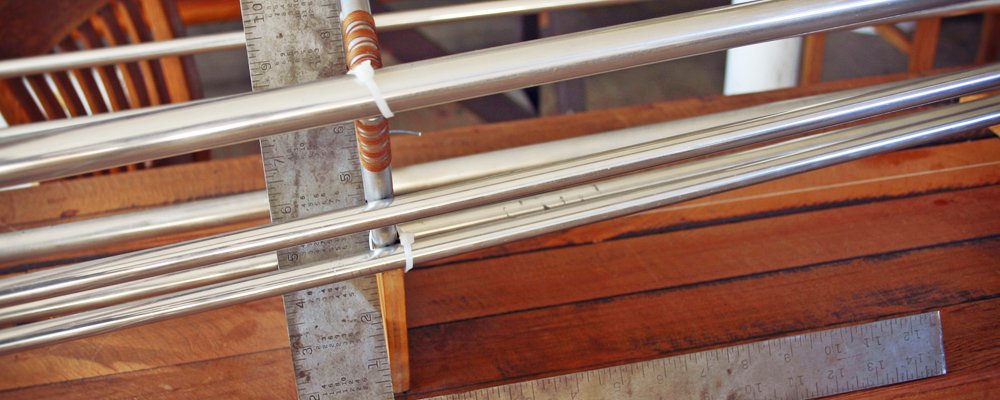
Measuring to length
The keel, stringers (I, II and III), gunwales, and deck sections are cut to the finished length indicated on the plans prior to bevelling.
- For the keel, stringers I, stringers II, and the forward deck, measure and cut to the length aft of station 9 from the station 9 mark.
- Both gunwales, stringers III, and the aft deck are measured and cut to the total length.
(See table above for stringer measurements)
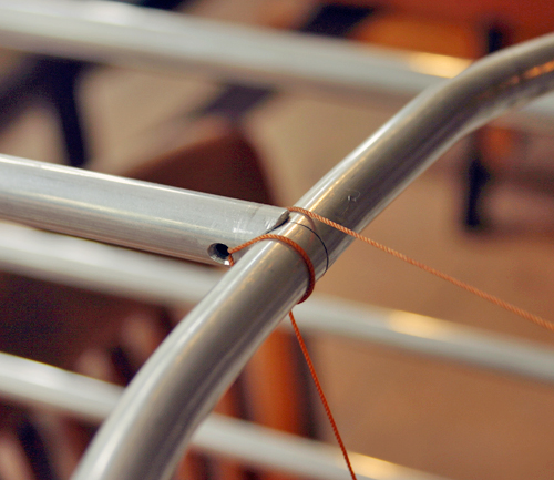
Slots
Both ends of the keel, the forward end of the gunwales, and the stern end of the aft deck section are slotted to ensure alignment and rigidity in the frame. Slot width is 0.16 cm and is cut using an adjustable speed router with a 3-pronged bit.
Keel
- Slot from the station 9 mark to 6.5 cm from the bow end.
- 2.5 cm from the stern end of the tubing, slot forward 28.3 cm.
Deck
From the stern end of the aft deck slot forward 8 cm.
Gunwales
At the bow end of each gunwale cut a 8 cm slot.
Bevelling
Prior to assembly the gunwales and deck sections are bevelled to fit adjoining flatware and tubing.
Gunwales
At the forward end of each gunwale, opposite the slot, file a 45° bevel inwards with a sharp file.
Gunwales (forward bevel)
Forward deck section (forward bevel)
Deck
- Referencing the plan, bevel the forward end (bow) of the forward deck section to the curve of the foredeck.
- At the aft end of the forward deck section and the forward end of the aft deck section a semicircle is filed for a close fit with the hatchway tubing. Use a 1/2" rat-tail file. Verify that the semicircle filed at the aft end of the forward deck section is perpendicular to the forward bevel.
Drain Holes
Marking
- Position stern flatware inside the aft keel slot.
- Approximately 45° from the vertical stern flatware, scribe a line 2 feet forward on both sides of the keel.
- With 14 drain holes per side, begin marking at the center of the forward two holes on the stern flatware along the scribed line. Moving aft, make a mark for every two holes on the stern flatware until the 5th hole fromt the end is reached.
- Repeat steps 2 and 3 for the other side of the keel.
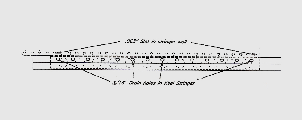
Drilling
- Use an awl and hammer to make an indentation at the center of each marked hole on the keel
- Use a drill press with a 3/16" bit at high RPM to drill each hole.
- Deburr each hole by using a countersink bit to recess the surface.
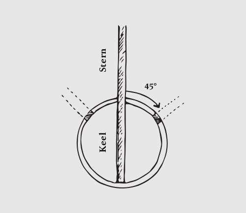
Aft view of the keel
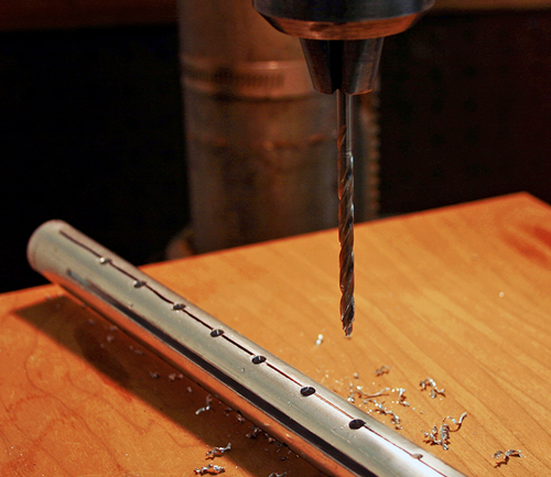
Drilling the holes
Pre-assembly
Strongback
In the full sized plans, for each station there is an outline for a strongback form. A table is built with the strongback stations (1-9) mounted at 1' intervals, aligned with a taut string through the centerline.
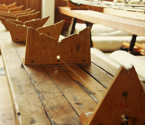
Strongback table
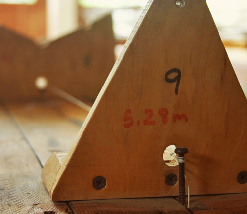
Align through the centerline
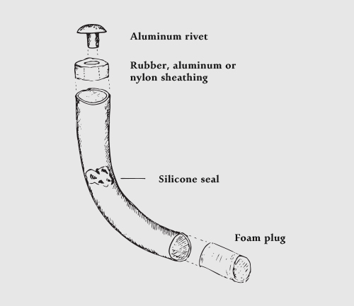
Plugs
| Materials | Type | Quantity | Size |
| Foam plugs | Rib frames | 26 | 1/2" diameter |
| Deck, stringers (I, II, III) | 16 | 1/2" diameter | |
| Gunwales, keel | 5 | 3/4" diameter | |
| Aluminum rivets | Keel | 1 | 3/4" diameter |
| Stringers (I, II, III) | 8 | 1/2" outer diameter | |
| Sheathing material for 1/2" and 3/4" rivets | |||
| Hemostat and pliers | |||
| Bore brushes (1/2" and 3/4") or steel wool | |||
| Silicone, clear | |||
Pre-assembly
Prior to final assembly, all rib frames and gunwales are plugged with foam and silicone to prevent water intrusion.
- Use a bore brush of the proper diameter, or steel wool and pliers to roughen the inner surface of the tubing ends.
- Apply a thin layer of silicone to a foam plug of the proper diameter, and insert into tubing end with a hemostat. Insert a blob after the foam plug to seal.
- Clean all surfaces thoroughly with acetone.
Note: Stringer ends are plugged and finished with a foam plug and aluminum rivet after the final assembly of the frame.
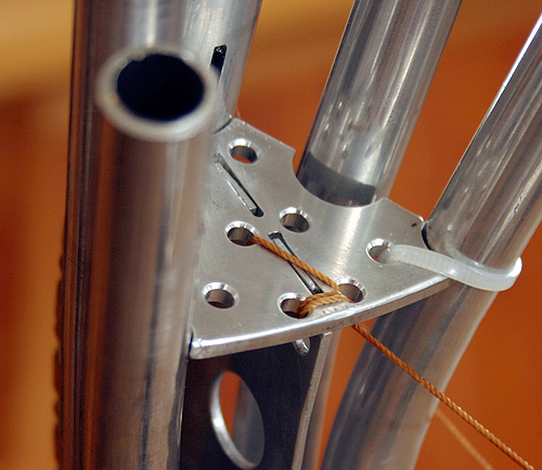
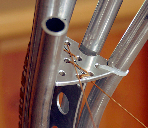
Stem and stern
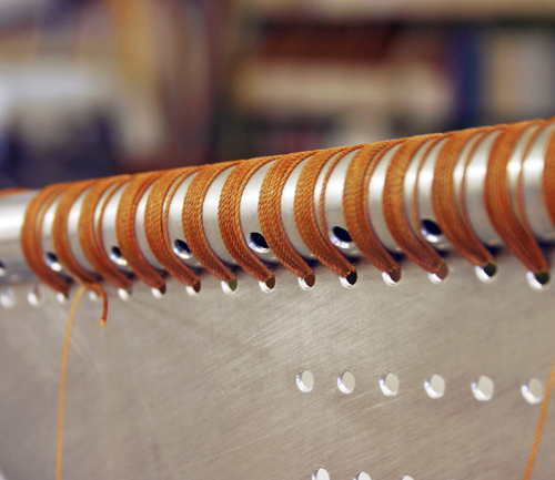
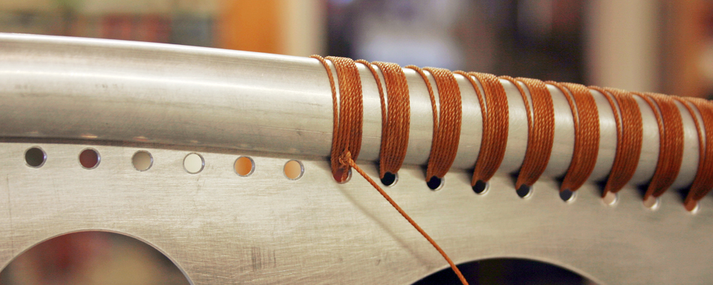
Lashing the stem
- Insert fabricated stem component into the forward keel slot by bending the curve outwards.
- Place the keel in a vise with the curve turned downwards.
- Cut a length of cordage (3 arm spans) and secure the end with a clove hitch around the keel and through the first hole on the stem component. Make 6-7 turns through each hole and around the keel, keeping the cordage tensioned.
- Repeat to the forward end of the keel, and finish with two half hitches around the lashings. Trim cordage and finish ends with a lighter.
Insert stem component into keel slot
Begin with a clove hitch through the first hole
Keep the cordage tensioned
Make 6-7 turns through each hole
Lashing the stern
- Rotate keel with the curve turned upwards, and insert the stern component into the aft keel slot.
- Cut a length of cordage (3 arm spans) and secure the end with a clove hitch around the keel and through the aftmost hole on the stern component. Make 6-7 turns through each hole and around the keel, keeping the cordage tensioned.
- Repeat to the forward end of the stern component, and finish with two half hitches around the lashings. Trim cordage and finish ends with a lighter.
Note: When lashing the stern component to the keel, align the lashings away from the drain holes.
Keep the cordage tensioned
Make 6-7 turns through each hole
Note: When the cordage becomes to short to continue lashing, trim a new length of cordage (3 arm spans) and attach to the remaining cordage with a sheet bend. Verify that the knot will be near the center of a hole on the next turn around the keel.
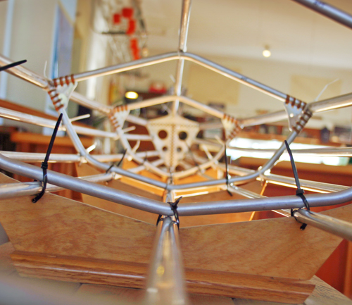
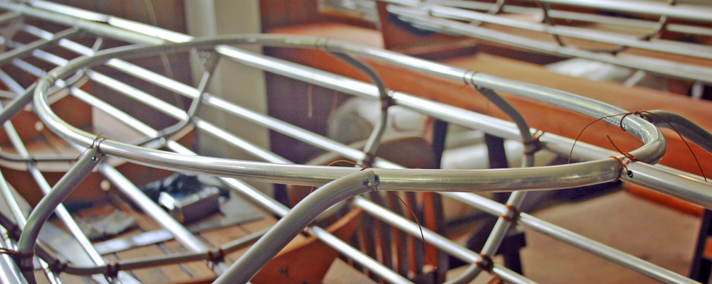
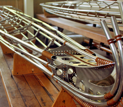
Frame alignment
Position the keel with the stem and stern bulkheads positioned at the station 9 and station 1 strongback forms. Secure the frame in place, wiring the keel to each strongback form.
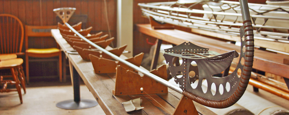
Laying the keel
Next, stringers II are secured with cable ties or wire to the stem, then along the strongback to the stern. Each rib frame is positioned at the proper strongback form, aligned perpendicularly to the table and secured to the keel and stringers II.
Attach stringers II to the frame
Align the rib frames with each strongback form
Position stringers I along the strongback, securing at each rib frame and to the stem and stern. Stand at the bow and ensure proper alignment of the keel and stringers. Secure the stemhead component to the stem and stringers. Attach the gunwales, deck sections, and stringers III to the frame.
Verify proper frame alignment
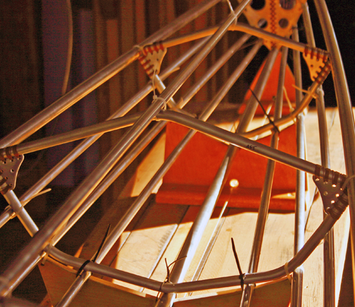
Secure frame with cable ties or wire at each intersection
Final Assembly
Stem
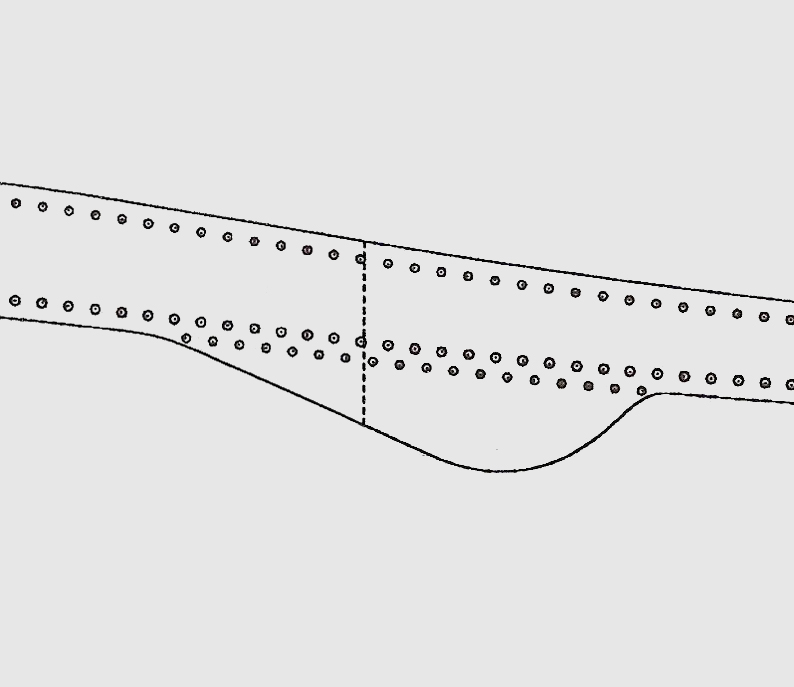
Each stringer is lashed to the stem, then along each rib frame to the stern. Inserted between stringer II and the stem (on both sides of the frame) is a spacer.
- For both sides of the frame, position a 1/8" spacer between stringer II and the stem flatware. Temporarily use a cable tie to hold stringers II together and the spacers in position.
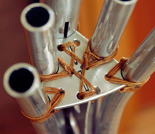
- Cut a length of cordage (approximately 4 yards) and clamp one end to the table. With the working end (starting at the aftmost hole on the top row), make 6-7 turns through each set of holes (top and center row), around both stringers II. At the forward set of holes, make an additional turn and thread through the loop (pulling tightly). Finish with two half hitches around the lashings for stringers II.
- Thread down through the forward center hole, and make 6-7 turns through each set of holes (center and bottom row), around both stringers I. At the aftmost set of holes, make an additional turn and thread through the loop (pulling tightly). Finish with two half hitches around the lashings for stringers I.
- Trim cordage and finish ends with a lighter.
Note: To make a spacer, place a scrap of 1/2" tubing in a vise and file one end with a 1/2" rat-tail file. Measure 1/8" from the inner curve of the semicircle and cut with a hacksaw.
1/8" spacer between stringer II and the stem
Lashings for stringers II
Starting the stringers I lashings
Finished stringer lashings at the stem
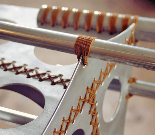
Bulkhead
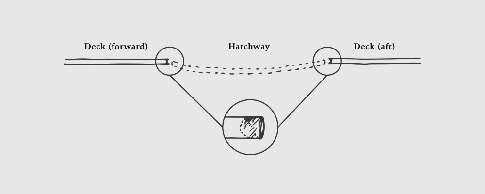
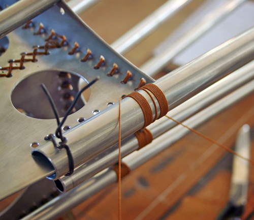
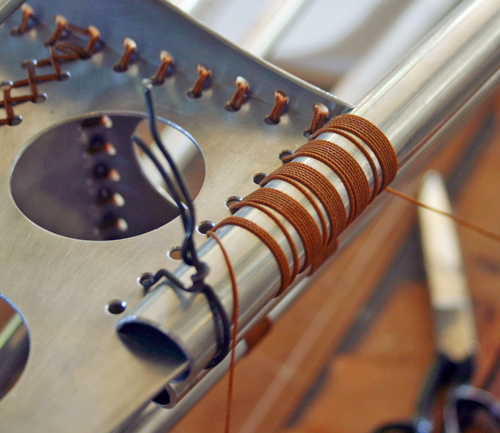
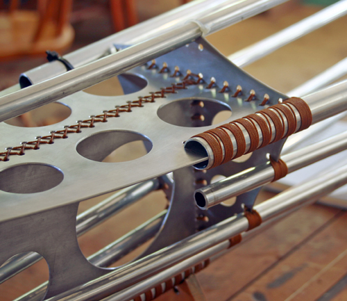
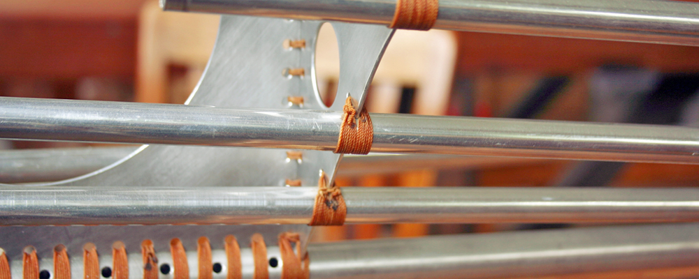
- Cut a length of cordage (approximately 1 yard) and clamp one end to the table. Thread the working end through the hole above the stringer at the bulkhead notch, and make 6-8 turns around the stringer on both sides of the bulkhead (forward and aft). Each turn is made inside (closer to the bulkhead) than the turn preceding it.
- Finish the working end of the cordage with two half hitches around the lashings at one side of the bulkhead. The cordage clamped to the table is finished in the same way (on the opposite side of the bulkhead).
- For stringers III, align the end 6.4 cm forward of the stem bulkhead prior to lashing.
- Trim cordage and finish ends with a lighter.
Note: For each pair of stringers, lash to the stem bulkhead on alternating sides of the frame to maintain proper alignment.
Start at the hole above the stringer
Make each turn inside the preceding turn
Finish with two half hitches close to the bulkhead
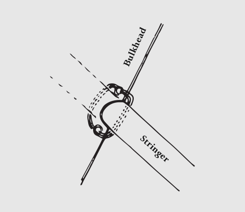
Stringer to bulkhead lashing diagram
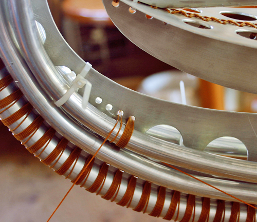
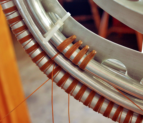
Gunwales
- Align each gunwale (with the slot pushed forward) to the notch on the foredeck edge. Wire securely into place.
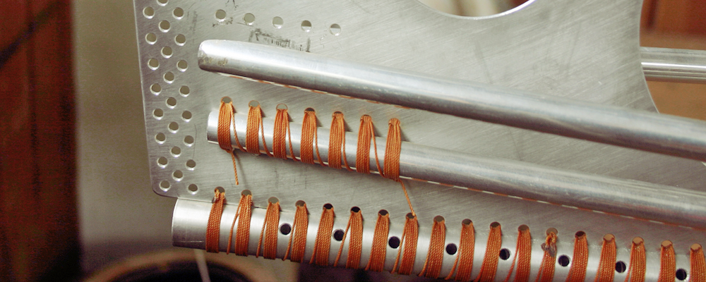
- Cut a length of cordage (approximately 3 arm spans), and clamp one end to the table. Thread the working end through the aftmost hole on the foredeck. Make 6-7 turns through each hole, around the gunwale.
- Finish the cordage ends with two half hitches around the lashings on the underside of the foredeck.
- Trim cordage and finish ends with a lighter.
Align both gunwales with the foredeck notch
Make 6-7 turns through each hole
Finished gunwale on port side of frame
Lashing the starboard side gunwale
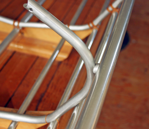
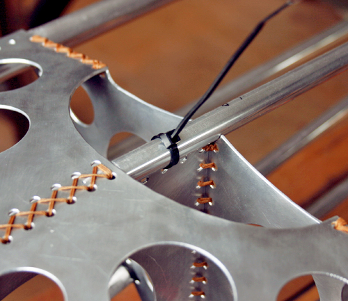
Rib frames
Prior to lashing ensure the rib frame is perpendicular to the strongback table using a large framing square. Lash rib frame intersections starting at the gunwale on one side of the frame, working down to the keel, then repeating on the opposite side.
Gunwales
- Cut a length of cordage (approximately 3 arm spans), and clamp one end to the table. Thread the working end through the corner hole on the rib frame gusset. Make 6-7 complete turns (around the gunwale, through the hole, and back around the gunwale). Each turn is made inside (closer to the gusset) than the turn preceding it.
- Finish the working end of the cordage with two half hitches around the lashings at one side of the gusset. The cordage clamped to the table is finished in the same way (on the opposite side of the gusset).
- Trim cordage and finish ends with a lighter.
Lash through the gusset and around the gunwale
Make each turn inside the preceding turn
Finish the cordage ends on opposite sides
Align lashings tightly to each other
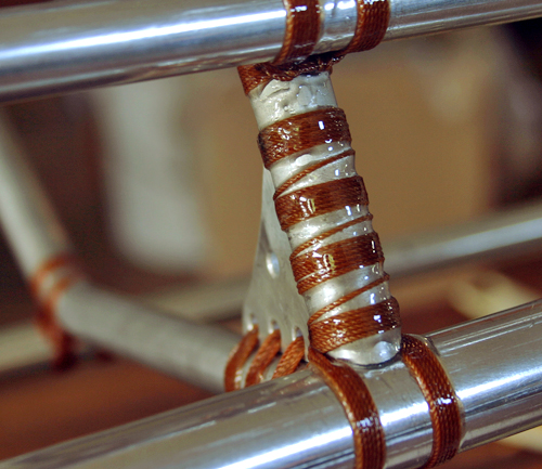
Stringers and keel
- Cut a length of cordage (approximately 3 arm spans), and clamp one end to the table. Make 6 complete turns around the stringer (or keel) and rib frame (see diagram), with each turn on the inside of the turn preceding it.
- Make 6 turns around the lashings (at the stringer and rib frame intersection).
- Finish the cordage ends with two half hitches around the lashings.
- Trim cordage and finish ends with a lighter.
Note: On both sides of rib frame 4.5, align a spacer between the gunwale and rib frame prior to lashing. To make the spacer, place a scrap of 1/2" tubing in a vise and file one end with a 1/2" rat-tail file. Measure approximately 3/16" from the inner curve of the semicircle and cut with a hacksaw. File the flat end with a 3/4" rat-tail file to fit the curve of the gunwale.
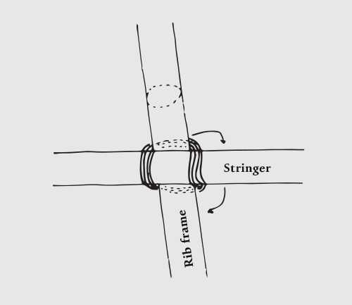
Stringer to rib frame lashing diagram
1/8" spacer between rib frame 4.5 and the gunwale
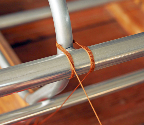
Make each turn inside the preceding turn
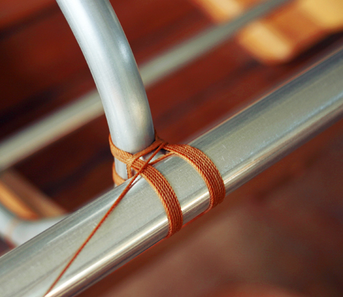
Tensioning the lashings
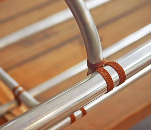
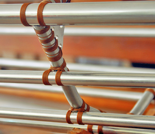
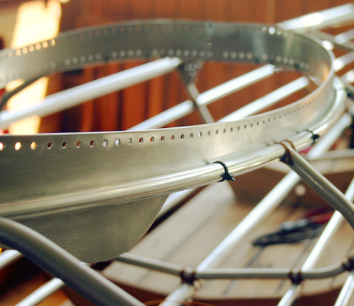
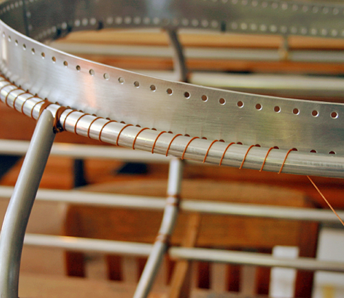
Hatchway
With rib frames 4, 4.5, and 5 permanently lashed, align the hatchway centered with the forward and aft deck sections and temporarily secure at each ribframe and deck intersection.
- Cut a length of cordage (approximately 2 arm spans), and clamp one end to the table. Make 6 complete turns - around the hatchway, through the hole in the rib frame, around the hatchway, and back through the hole. Each turn is made on the inside of the turn preceding it. At the deck and hatchway intersections, make 6 turns around the deck tubing before finishing.
- Finish the cordage ends with two half hitches around the lashings.
- Trim cordage and finish ends with a lighter.
Note: Each rib frame is lashed on both sides to ensure proper alignment of the hatchway. Rib frame 4.5 is completed before rib frames 4, 5, and the deck sections.
Lash around the hatchway and through the hole
Make each turn inside the preceding turn
Make 6 turns around deck tubing before finishing
Align hatchway to the centerline of the frame
Deck
Stem
- Position the forward deck section along the frame centerline.
- Cut a length of cordage (approximately 4 yards), and clamp one end to the table. With the working end (starting at the forward two holes on the foredeck), lash aft (8 holes), making 6-7 turns through each hole and around the deck tubing.
- To secure the lashings, make 8 turns around the deck tubing.
- Finish the working end by making a turn and pulling the end through before tightening. Repeat for a secure knot. The cordage clamped to the table is finished with two half hitches around the forward lashings.
- Trim cordage and finish ends with a lighter.
Make 6-7 turns through each hole
Forward deck to foredeck lashings
Bulkhead
- Cut a length of cordage (approximately 1 yard) and clamp one end to the table. Thread the working end through a hole at the stem bulkhead notch, and make 6-8 turns around the deck on both sides of the bulkhead (forward and aft). Each turn is made inside (closer to the bulkhead) than the turn preceding it.
- Finish the working end of the cordage with two half hitches around the lashings at one side of the bulkhead. The cordage clamped to the table is finished in the same way (on the opposite side of the bulkhead).
Stern
- Wire the aft deck section to the stern compontent, with the deck pulled tightly to the quarterdeck.
- Cut a length of cordage (approximately 3 yards) and clamp one end to the table. Thread the working end through the aftmost hole (below the deck section) on the stern, and make 6-7 turns around the deck and through each hole.
- To secure the lashings make 8 turns around the deck tubing.
- Finish the working end by making a turn and pulling the end through before tightening. Repeat for a secure knot. The cordage clamped to the table is finished with two half hitches around the aftmost lashings.
Pull aft deck tightly to the quarterdeck
Make 6-7 turns through each hole
Stemhead
Stem
- Cut a length of cordage (approximately 1 yard) and clamp one end to the table. With the working end, make a few turns through the aftmost two holes on the stemhead centerline and lash forward, crossing over then straight.
- At the end of the row, make a few turns to secure the first row of lashings. Return to the beginning of the row, crossing over the first pass of lashings.
- At the aftmost two holes make a few turns and finish both ends with two half hitches around the lashings. Trim cordage and finish ends with a lighter.
Lash through the holes on the stem edge
Keep the cordage tensioned
Stringers
- Cut a length of cordage (approximately 1 yard) and clamp one end to the table. Thread the working end through the hole nearest to the stringer on the stemhead, and make 6-8 turns around the stringer above and beneath the stemhead. Each turn is made inside (closer to the stemhead) than the turn preceding it.
- Finish the working end of the cordage with two half hitches around the lashings at one side of the stemhead. The cordage clamped to the table is finished in the same way (on the opposite side of the stemhead).
- Repeat steps 2 and 3 for each stringer at the stem, alternating sides to maintain alignment.
- Trim cordage and finish ends with a lighter.
Stern
Bulkhead
- Cut a length of cordage (approximately 1 yard) and clamp one end to the table. Thread the working end through the hole above the stringer at the bulkhead notch, and make 6-8 turns around the stringer on both sides of the bulkhead (forward and aft). Each turn is made inside (closer to the bulkhead) than the turn preceding it.
- Finish the working end of the cordage with two half hitches around the lashings at one side of the bulkhead. The cordage clamped to the table is finished in the same way (on the opposite side of the bulkhead).
- Trim cordage and finish ends with a lighter.
Stringer ends
- After the stemhead has been lashed, the aft ends of stringers I and II are bevelled to the angle of the vertical stern component. For each stringer, draw this angle (at the length indicated in the full sized plans) with a permanent pen.
- Bevel to the marked line with a flat file, frequently verifying that the stringer will lay flat to the stern.
- Deburr and plug tubing ends.
- Cut a length of cordage (approximately 4 yards) and clamp one end to the table. Thread the working end through the holes at the aft end of the stern and lash forward, making 6-7 turns around the stringer on both sides of the stern component.
- Finish the cordage with two half hitches around the lashings, trim, and melt ends with a lighter.
Note: It is important to lash the stringer ends forward to aft, else the lashings will bunch up to the side of each hole rather than lay flat.
Gunwales
- Cut a length of cordage (approximately 3 arm spans), and clamp one end to the table. Thread the working end through the aftmost hole on the quarterdeck. Make 6-7 turns through each hole, around the gunwale.
- Finish the cordage ends with two half hitches around the lashings on the underside of the quarterdeck.
- Trim cordage and finish ends with a lighter.
- With a flat file, bevel the aft end of each gunwale to the curve of the quarterdeck edge.
Cockpit coaming
- Mark the center of the cockpit coaming, align mark to forward deck, and attach with wire or cable ties.
- Wire the coaming to the curve of the hatchway, aligning the lower edge of the coaming to the bottom of hatchway tubing.
- Cut a length of cordage (approximately 3 arm spans), and clamp one end to the table. Begin lashing at the aft side of the cockpit, making a single turn through each hole, around the hatchway tubing. Make 3 passes around the hatchway, keeping the cordage tensioned.
- Finish the cordage with two half hitches around the lashings, trim, and melt ends with a lighter.
Wire coaming flatware to the hatchway
Make a single turn through each hole
Make 3 passes around the cockpit
Align lashings tightly to each other
Inside
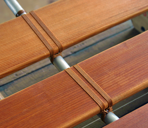
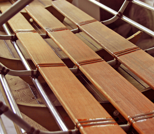
Floorboards
Shaping and finishing
- Select 3 boards of cedar wood planed to approximately 1/2" in thickness. Each board is 3-4" wide and 68" in length (to span from station 2 to station 7).
- With a pencil, draw a curved edge on each board and a gradual taper on the outer planks towards the bow.
- Carefully cut along this line with a bandsaw, and curve the edges with a router.
- Sand planks by hand with 100 then 150 grit sandpaper until the edges and surface are even and smooth.
- Apply 5 coats of teak oil to the planks with a cotton cloth, allowing time to dry between coats.
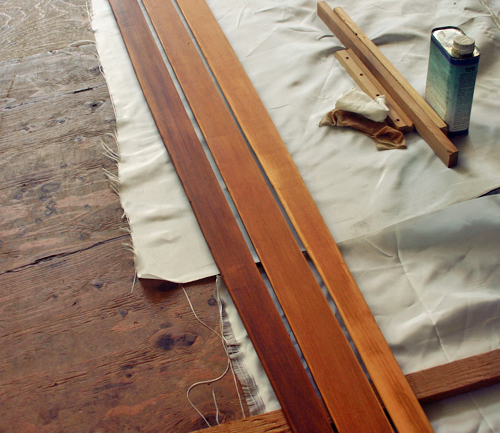
Apply 3 coats of teak oil
Align floorboards and temporarily secure in place
Lashing
- Position the middle floorboard between station 2 and station 7, centered along the keel. Temporarily secure to the frame with short lengths of twine.
- Wind a large net needle with a length of cordage (approximately 3 arm spans), and clamp the end to the table. Make 6 complete turns around the floorboard and rib frame, with each turn on the inside of the turn preceding it.
- Make 6 turns around the lashings (at the floorboard and rib frame intersection).
- Finish the cordage ends with two half hitches around the lashings.
- Repeat steps 2 - 4 for each floorboard and rib frame intersection.
- Position the outer floorboards between station 2 and station 7, approximately an 1" from the middle floorboard. Temporarily secure to the frame with short lengths of twine.
- Repeat steps 2 - 5 for the outer floorboards.
- Trim cordage and finish ends with a lighter.
Note: Each floorboard is lashed to all rib frames except station 4.5.
Lashing with a large net needle
Make each turn inside the preceding turn
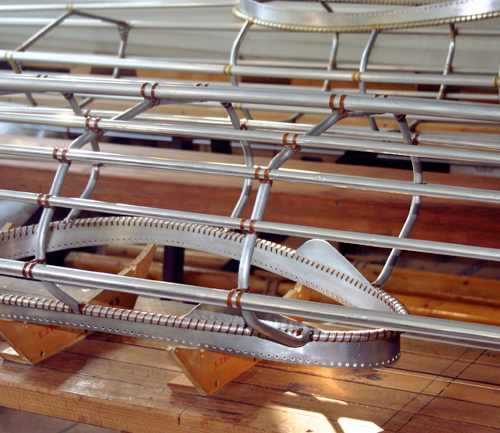
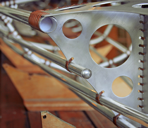
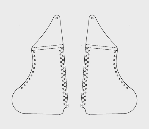
Foot braces
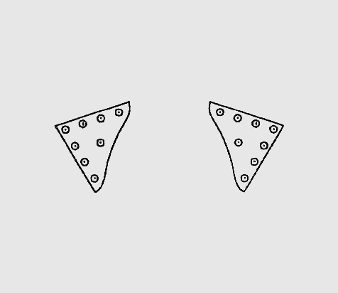
Fabricating
- With a pencil, trace the forward and aft foot brace mounting templates onto 9/64" sheet aluminum. Repeat for the other side of the frame.
- Carefully cut around each template with a bandsaw. Mark 6 evenly spaced holes at both ends of each mounting component (at the position on the plans) and drill using a 1/8" bit. Countersink holes to remove the rough edges for the lashings.
- For each mounting component, mark the horizontal line (bend mark) at the position on the plans.
- Measure to the center of the longer side on each component, and drill a hole to accommodate the bolt for the foot brace.
- Secure component in a vise with the bend mark aligned 1 mm below the top edge of the vise. Bend flatware 30° using a rubber mallet. Adjust component with the bend mark aligned at the top edge of the vise and bend another 30°. The final bend to 90° is made with the bend mark aligned 1 mm above the top edge of the vise.
- Deburr and polish edges and surfaces.
Note: Bending in increments of 30° to form a radius curve prevents the aluminum from fracturing with a single 90° bend.
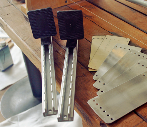
Aluminum mounting components and foot braces
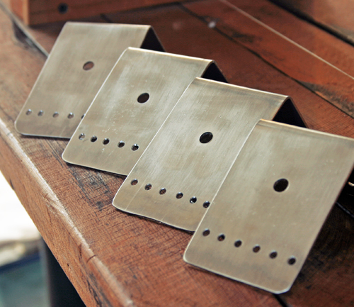
Holes for lashings and foot brace bolts
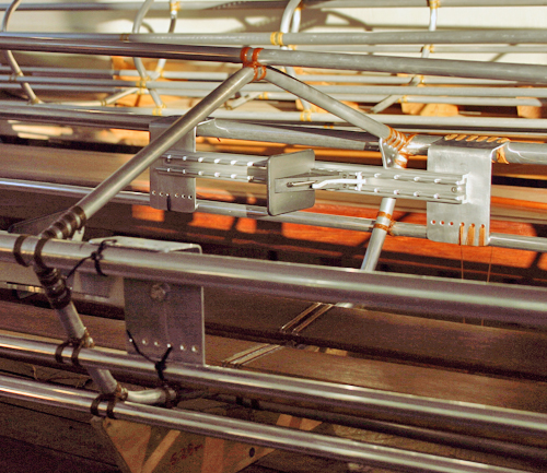
Installing
- Install foot braces on mounting components, with the foot peg adjusted to the middle setting.
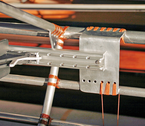
- 3" forward of the aft side of the cockpit, measure forward 42". For both foot braces, align the foot peg to this position, and mark both sides (forward and aft) of the mounting components on the gunwales. Secure the foot braces temporarily to the frame with wire or cable ties.
- Cut a length of cordage (approximately 4 yards), and clamp one end to the table. Thread the working end through the aftmost hole on the mounting component (starting with the upper row), and make 6-7 turns through each hole.
- Finish the cordage ends with two half hitches around the lashings.
- Trim cordage and finish ends with a lighter.
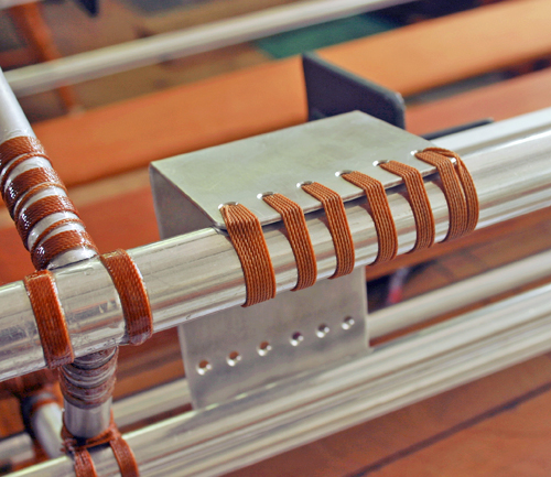
Upper row to gunwale lashings
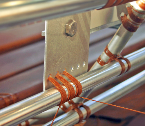
Lower row to stringer III lashings
Post-assembly
Epoxy the lashings
With a cotton cloth, apply acetone to the lashings to remove oil and dust. Rotate the frame, and align lashings. Rotate again, and adjust stringers for proper frame alignment.
Apply a coat of unthickened epoxy to the lashings using a disposable foam brush. Work with small batches, removing excess epoxy from the tubing with acetone. Epoxy alternating sides of the frame (starting at the stem working aft) to maintain proper alignment.
Allow 2-3 days for the epoxy to cure. Rotate the frame, and using a sharp razor blade remove any hardened epoxy drips on the bottom of the lashings.
Stringer ends
The forward end of the keel, stringers I and stringers II, and both ends of stringers III are finished with an aluminum rivet and foam plug.
Stemhead
Measure 1/2" above stemhead component, and mark each stringer and keel with a permanent pen. Cut at mark with a hacksaw, parallel to the angle of the stemhead surface. Deburr and finish tubing ends.
Plugging
- Apply a thin layer of silicone to a foam plug of the proper diameter, and insert into tubing end with a hemostat. Insert a blob after the foam plug to seal. Clean tubing surfaces with acetone.
- Select an outer sheath with an inner diameter approximately the size of the rivet shaft. Cut sheathing to a length 1/16" shorter than the shaft.
- Insert rivet into sheathing and hammer the rivet base to expand the shaft. Firmly wedge plug into tubing end with rubber mallet.
Note: Aluminum, rubber, plastic or nylon with the proper diameter may be used as sheathing.
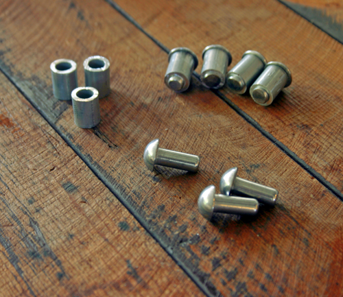
Rivets and outer sheathing
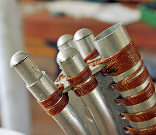
Finished tubing ends at the stemhead
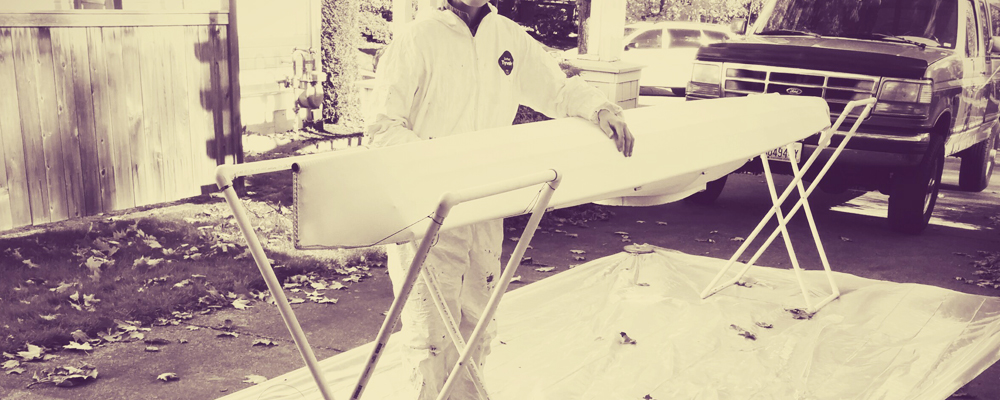
Skin
Before sewing the skin, the strongback form edges are padded to prevent the fabric from chafing. Measure the upper edge of each strongback form and cut a section of clear hose to slightly longer than this length. Slice down the length of tubing with a razor blade, and center on the strongback form.
Sewing
- Rotate the frame, and align a length of 16-oz polyester cloth (18.5') over the hull, centered along the keel and positioned evenly forward and aft. Trim a length of twine and run a loose basting seam around both gunwales to hold the fabric in place.
- With the frame turned right side up, the fabric is tensioned to the cockpit coaming and losely stitched to the perimeter of the hatchway.
- Tension the fabric on both sides of the hull, and mark the centerline by gently running a piece of colored chalk along the deck tubing, working from the forward side of the cockpit to the stem bulkhead (deck to bulkhead lashing). Repeat from the aft side of the cockpit to the stern quarterdeck end.
- Trim fabric to a 1/2" seam allowance on both sides using a hot knife (to seal the edges). Always wear a respirator throughout this process. After trimming, hold the sides together with large steel pins.
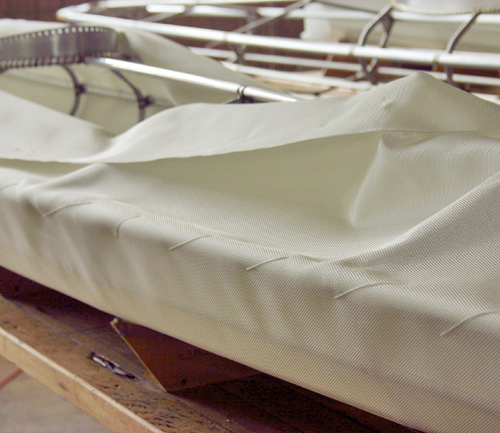
Align the fabric and attach to both gunwales
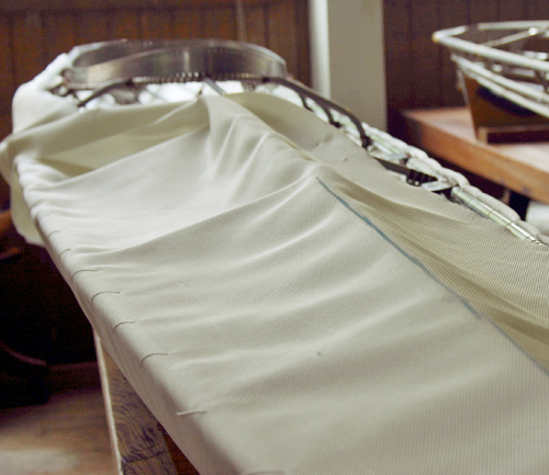
Mark the frame centerline on both sides of the fabric
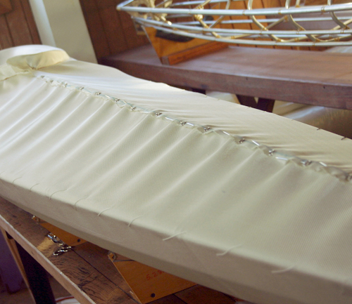
Hold the fabric together with large steel pins.
Begin deck seam a few inches forward of the cockpit
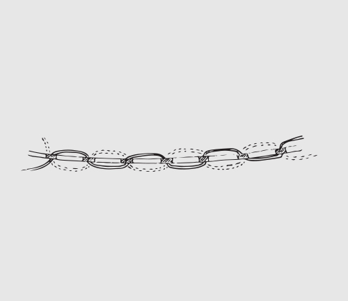
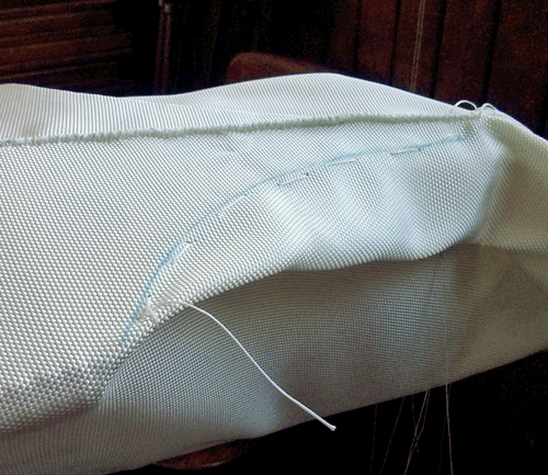
Deck
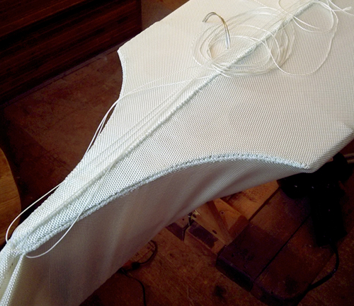
- Cut a length of cordage (approximately 4 yards), and thread each end with a large, curved needle.
- A few inches forward of the cockpit, fold fabric to the centerline mark on both sides. Pull the sides together and thread both needles through the fabric from underneath, with the cordage pulled evenly through on either side.
- With one side of the cordage, make 5 stitches along the deck, spaced 1/8" apart. Pull each stitch tightly, with the thread exiting the fabric approximately 1/8" from the folded edge. Repeat with the other side of the cordage, crossing over then straight underneath (above the deck tubing).
- At the stem bulkhead, finish each end of the cordage by making a loop through the fabric (as if making another stitch) and pulling the end through. Pull the cordage tightly and melt ends to the fabric with a hot knife.
- Repeat steps 2-4 for the deck seam aft of the cockpit.
Note: The fabric should be tensioned when sewn, though prior to ironing if a coin bounces when dropped onto the skin, the fabric is too tight.
Make several stitches with one side of the cordage
Tension the fabric and tighten each stitch
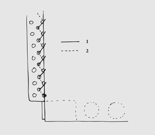
Hatchway
- Remove the basting stitch on both sides of the cockpit.
- Cut a length of cordage (3 arm spans), and thread one end with a long, straight needle and finish the other end with a knot.
- Thread the cordage through a hole on the lower row of the cockpit coaming (approximately 6" from the aft end of the cockpit) and work forward to approximately 6" from the forward end of the cockpit. Finish the cordage by making a loop through a hole (as if making another stitch) and pulling the end through.
- Repeat steps 2-3 for the same side of the cockpit, offsetting the second seam by a stitch and working aft (see diagram).
- For the opposite side of the cockpit, repeat steps 2-4.
Finished hatchway seam
Offset the stitches
Deck/Hatchway
- Hatchway seam: Cut a length of cordage (approximately 1 yard), and thread one end with a long, straight needle and finish the other end with a knot. Thread the cordage through a hole on the lower row of the cockpit coaming, a few inches forward of where the hatchway seam ended on one side of the cockpit. Repeat for the other side of the cockpit.
- Deck seam: Cut a length of cordage (approximately 2 yards), and thread each end with a large, curved needle. Fold fabric to the centerline mark on both sides (trim any excess fabric to leave a 1/2" seam allowance). Pull the sides together and thread both needles through the fabric from underneath (a few inches forward of where the deck seam ended), with the cordage pulled evenly through on either side.
- Make a few stitches along the deck seam, followed by a few stitches on either side of the cockpit. When the seams converge at the deck to hatchway intersection, secure the deck seam in place and finish the hatchway seams.
- Continue the deck seam to an inch beyond the upper cockpit coaming edge, and finish the end by making a loop through the fabric (as if making another stitch) and pulling the end through. Pull the cordage tightly and melt ends to the fabric with a hot knife.
- Repeat steps 1-4 for the opposite end of the cockpit.
Alternate deck and hatchway seams
Finish deck seam an inch beyond the cockpit edge
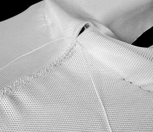
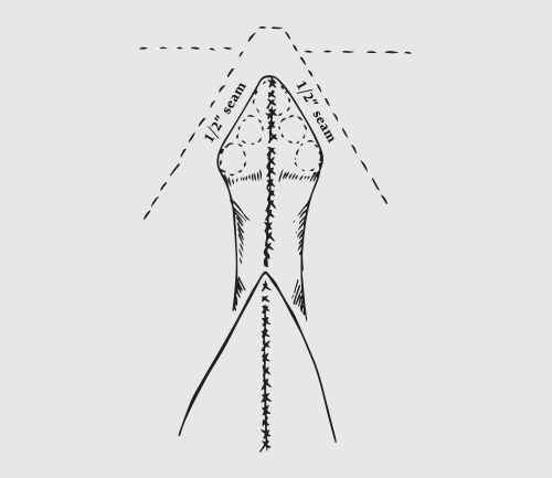
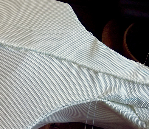
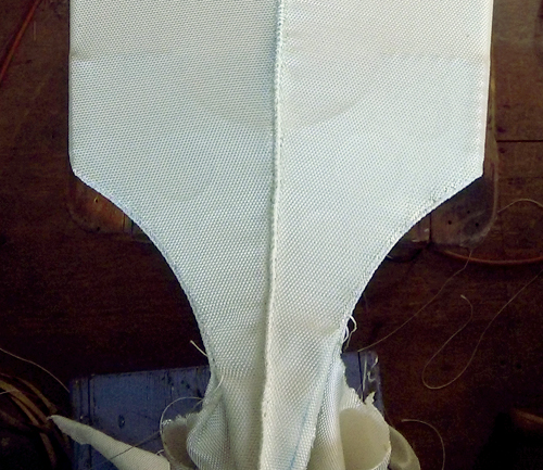
Stem
- Temporarily stitch the deck seam to the end of the foredeck. Pull fabric loosely under the foredeck, and stitch both sides together from the corner of the bifurcated bow to the aft side of the stemhead (centered vertically in the bifurcation in the stem). Tension fabric along the keel, and stitch from where the fabric is loose to the forward side of the stemhead.
- With a hot knife, cut through the temporary stitch along the bifurcated stem, and remove the excess fabric in front of the foredeck leaving 1/2" of seam allowance.
- Cut a length of cordage (3 arm spans), and thread each end with a large, curved needle. Remove the temporary stitches at the deck seam and fold fabric to the centerline mark on both sides of the deck tubing. Pull the sides together and thread both needles through the fabric from underneath, with the cordage pulled evenly through on either side.
- Sew to the foward end of the deck, making a few stitches with one side of the cordage before finishing the seam with the other side. Continue stitching along the bifurcated stem to the forward side of the stemhead, aligning the seam at centerline with the deck seam. Finish the seam with a secure knot.
- Trim the excess fabric below the temporary stitches at the keel, leaving 1/2" of seam allowance.
- Cut a length of cordage (3 arm spans), and thread each end with a large, curved needle. Remove the temporary stitches along the keel. Thread both needles through the fabric at the bottom of the keel, with the cordage pulled evenly through on either side.
- Sew along the bottom of the keel (aligning the seam to the centerline), making a few stitches with one side of the cordage before finishing the seam with the other side. Finish the seam with a secure knot at the forward side of the stemhead.
Note: The photo shows the keel seam on the side of the stem, and this is the result of a mistake made when trimming the fabric. If done properly, the keel seam is sewn along the base of the stem at the keel centerline.
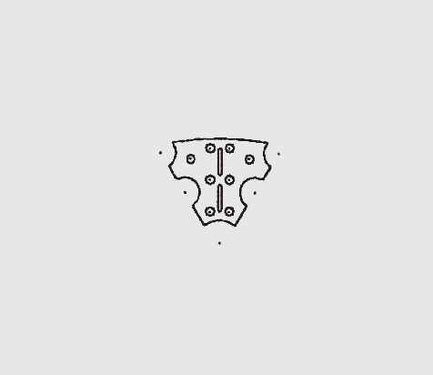
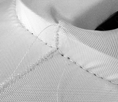
Stemhead
- Align the inner stem seam at the centerline of the stemhead. Make a few temporary stitches to hold the fabric in place where the seams intersect at the keel stringer.
- Draw a line on both sides of the fabric from the keel to stringer II. With a hot knife, trim fabric around the stemhead, leaving 1/2" of seam allowance outside of the chalked line (see diagram). Cut the fabric perpendicularly to the keel seam 1/2" beyond where it intersects with the keel stringer.
- Cut a length of cordage (1 yard), and thread each end with a large, curved needle. Remove temporary stitches and fold both edges of the fabric to the chalked line. Thread both needles through the fabric at a corner of the stemhead, with the cordage pulled evenly through on either side.
- Sew around the perimeter of the stemhead, making a few stitches with one side of the cordage before finishing the seam with the other side. Finish the seam with a secure knot at the opposite corner.
Trim fabric to 1/2" from the edge of the stemhead
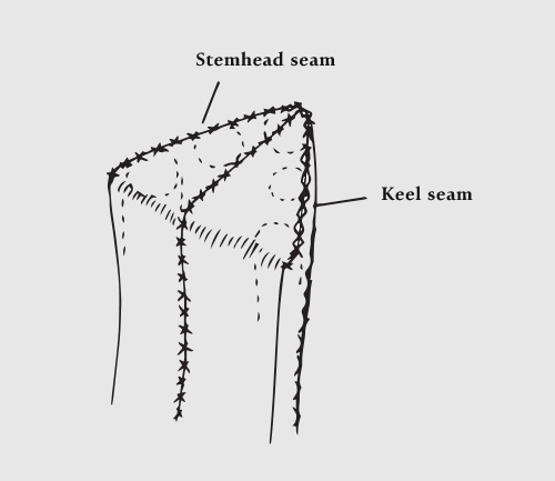
Align inner stem and keel seams to the centerline
Quarterdeck
- Align the deck seam to the frame centerline, and mark fabric along the quarderdeck edges with chalk. Hold fabric in place with loose stitches, and use a hot knife to cut 1/2" from the chalked line.
- Cut a length of cordage (3 yards), and thread each end with a large, curved needle. Fold both edges of the fabric to the chalked line. Thread both needles through the fabric (near the aft end of the gunwale), with the cordage pulled evenly through on either side. Repeat for the other side of the quarterdeck.
- When sewing the quarterdeck seams, alternate sides to maintain alignment of the deck seam. For each side, make a few stitches with one side of the cordage before finishing the seam with the other side. Align the seam to just below the quarterdeck edge.
- Continue both seams to the aft end of the quarterdeck, and finish with a secure knot.
Mark quarterdeck edges with chalk
Alternate sides to maintain deck seam alignment
Stern
- Fold fabric at the stern to the second column of holes, and mark the edge with chalk. Use a hot knife to cut 1" from the chalked line.
- Cut a length of cordage (3 yards), and with the fabric folded to the chalked line on both sides, thread through the bottom hole (third column). With the cordage pulled evenly through on either side, make a few turns (through column 2 and 3) to secure fabric to the frame.
- Lash diagonally through hole columns 2 and 3 with both sides of the cordage. Continue upwards to the end of the quarderdeck seams, and finish lashings with a secure knot.
Stern seam diagram
Lash diagonally through hole columns 2 and 3
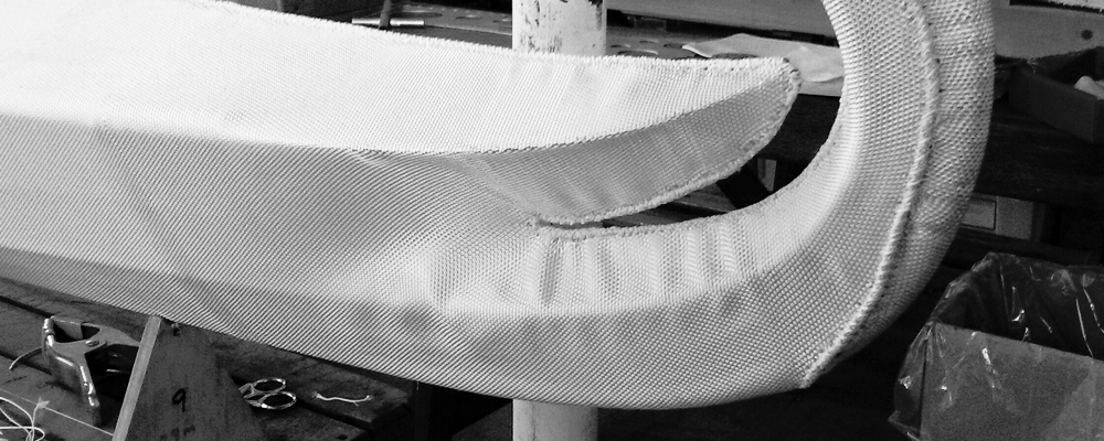
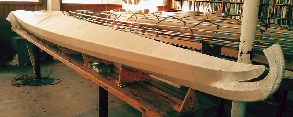
Ironing
Use an iron on medium heat to tighten the skin to the contour of the frame. Start at the cockpit, frequently alternating sides to ensure the deck seam remains centered as the skin tightens. Iron forward to the stem, allowing the fabric to shrink tightly to the stem and foredeck.
Rotate the frame and iron the hull, alternating sides to maintain even tension throughout the skin. With the frame turned right side up, iron around the cockpit until the skin shrinks tightly to the coaming. Trim skin flush to the cockpit rim with a hot knife.
Note: When finished, the skin should have the tension of a drum and a coin should bounce when dropped.
Sealing
Near the keel stringer where the fabric is sewn to the stern there is a space that forms when the skin is finished. Fill a syringe (select one with a large orifice diameter) with 5200 sealant. Tape around the keel and other exposed metal surfaces with masking tape. Inject sealant into the space on both sides of the stern to seal.
Note: Apply additional sealant to any gaps or spaces larger than a pinhead in the skin seams.
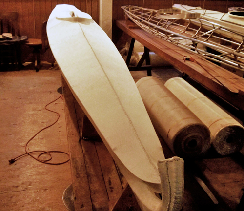
Ironed skin
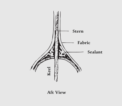
Sealing the stern
Finishing
Deck hardware
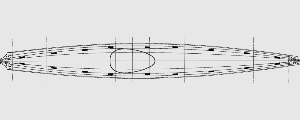
- Cut 18 sections of tubing (0.45" outer diameter), 4 cm long with a bandsaw or hacksaw. Finish the tubing ends using a flat file for the outer edge, and a swivel head deburring tool for the inner edge. Position 10 guides forward of the cockpit and the remaining 8 aft, spaced evenly (see diagram).
- Cut a length of cordage (4'), and thread the end with a small, curved needle. Position the deck fitting approximately 5/8" from the outer frame edge (parallel to the gunwale). Secure an end of the cordage by making a turn around the tubing and pulling the other end through the loop.
- Make 4 diagonal then straight turns around the tubing, spaced evenly.
- At the end of the tubing, make 2 straight turns to secure the lashings, and repeat step 3 in the opposite direction. Back at the starting end, make 2 straight turns and finish with two half hitches around the lashings (see diagram).
- Repeat steps 2-4 for each deck fitting.
Note: Position forward and aft deck fittings at an inward angle to the gunwale, approximately 2" from the deck seam.
Secure an end of the cordage
Make 4 diagonal then straight turns around the tubing
Lash in the opposite direction
Finish lashings with two half hitches
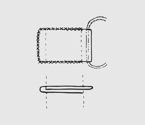
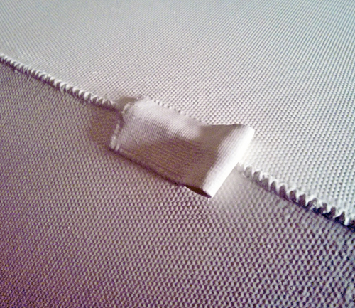
Rudder Control
Cut a length of nylon webbing (5") and melt the ends with a hot knife. Fold the ends under (see diagram), and position 2' forward of the cockpit centered over the deck seam. Sew the webbing edges to the skin, leaving one side open for the rudder control line.
Painting
| Supply | Type | Quantity |
| Flexibar Buoy Coating | White | 2 gallons |
| Plastic drop cloth | 10' by 25' | 1 |
| Roller frame | 4" | 1* |
| Roller covers | Synthetic, 4" | 6* |
| Paint tray | Standard, 11" by 17" | 1 |
| Paint tray liners | Standard, 11" by 17" | 6 |
| Safety gear (3M chemical respirator, Tyvek suit, nitrile gloves, protective glasses) | ||
| Masking tape | ||
| Cotton rags | ||
* This quantity is for a single person and must be doubled if two people are painting the skin (recommended).
Preparation
Apply masking tape to the inner cockpit coaming rim and the exposed metal surfaces at the stern and keel. Tape a sheet of plastic (a trash bag works) inside the cockpit to protect the interior from paint. Cover the floor in the painting area with a plastic drop cloth (I would advise painting outside, as the paint has a very powerful odor).
- Stir paint according to the directions, and use a small measuring cup to transfer approximately 2 cups of paint into the paint tray (remember to use a liner). Insert a new roller cover on the roller frame, thoroughly saturating it with paint.
- With the frame turned right side up, start at the stern and work forward to the stem. Apply paint directly to the seams while the roller cover is saturated, smoothing the paint around the deck fittings and into the hatchway seam. Allow a finished coat to dry for 10 minutes. Dispose of used paint tray liner and roller cover.
- Repeat steps 1 and 2 until 3 coats have been applied to both the deck and hull.
- After all coats have been applied, remove tape and plastic sheet from the cockpit and stern. Allow the paint to cure for the specified duration.
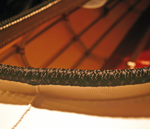
Cockpit rim
- Finish one side of a 6' length of 3/4" braided nylon rope with a hot knife. Align this end to the deck seam (aft of the cockpit) and use c-clamps to hold the rope in position around the coaming, positioned slightly above the upper edge of the cockpit rim.
- Cut a length of cordage (approximately 4 yards), and secure the end at the inner aft side of the coaming.
- Make a single turn through each coaming hole and around the rope, pulling cordage tightly and aligning the lashings.
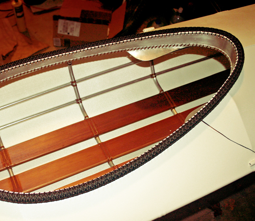
- When back at the aft end of the cockpit, mark the long end of the rope to the finish length and cut carefully with a hot knife. With a short length of cordage, secure the rope ends together. Finish the first pass around the cockpit.
- Continue lashing around the cockpit until 3 passes have been made.
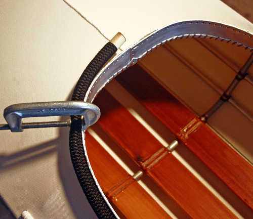
Position rope around cockpit rim
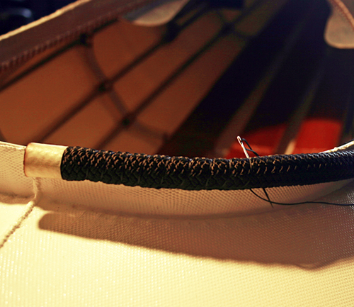
Make a single turn through each hole
Rudder
Fabrication
- For each rudder quadrant, mark the horizontal lines (bend marks) at the position on the plans.
- Secure component in a vise with the upper bend mark aligned to the top edge of the vise. Bend flatware 30° using a rubber mallet. Adjust component with the top edge of the vise aligned between the bend marks and bend another 30°. The final bend to 90° is made with the lower bend mark aligned to the top edge of the vise.
- Repeat step 2 for the other rudder quadrant, bending in the opposite direction.
- Apply silicone evenly to the inner surfaces of the rudder quadrants. Press the components together, align the edges, and secure in place with c-clamps. Allow sealant to dry for 24 hours.
- Remove silicone from metal surfaces with fine grit sandpaper, and from lashing holes with a drill bit or nail.
Horizontal lines (bending marks)
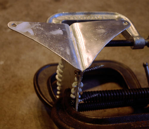
Attach the rudder quadrants with silicone
Lashing
- Lash through the holes at the aft edge of the rudder quadrants with a length of cordage (approximately 1 yard). Trim cordage and finish ends with a lighter.
- Cut a length of cordage (approximately 4 yards) and secure an end to the outer hole on the stern (first row, first column). Lash the rudder to the stern using a figure eight stitch through the outer holes on the stem and rudder components.
- Thread the cordage through one side of a hole on the rudder, back around the forward edge of the rudder, and through the opposite side of the hole on the same row of the stern.
- Secure the lashing with a few turns through the hole (on the current row) and the hole beneath it.
- Repeat steps 3 and 4 to the bottom row of holes. At the bottom row, secure lashing with a knot and finish ends with a lighter.
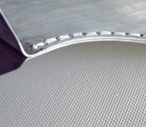
Lashing on aft end of rudder
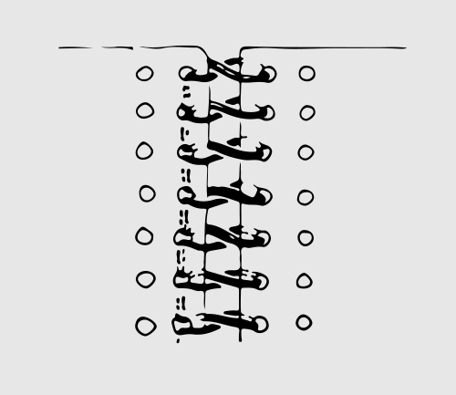
Figure eight stitch
Deck Rigging
| Material | Quantity | ||
| 5/16" nylon shockcord | 76' | ||
| 1/8" polyester rope | 30' | ||
| 1/4" polyester rope | 8" | ||
| 1/4" heat-shrink tubing | 4" | ||
| Shackle, pulley, or o-ring | |||
| Electrical tape | |||
Deck lines
- Two lengths of shockcord are used for the deck rigging, composing the perimeter and inner lines.
- First run the perimeter line, tensioning the shockcord slightly past neutral and cut to the proper length (with the ends centered between the aft deck fittings). Melt the ends to prevent the sheath from unraveling.
- Cut a 2" length of heat-shrink tubing and thread onto one end of the perimeter line. Sew the perimeter line ends together securely, and shrink the heat-shrink tubing over the splice.
- Find the center of the remaining shockcord (this is the inner line). Position (underneath the perimeter line) beneath the deck fittings second from the forward set.
- Run one side of the inner line around the nearest deck fitting (counterclockwise if on the starboard side, clockwise if on the port side), then aft to the deck fitting on the opposite side.
- Repeat with both ends of the inner line, until the deck fittings second from the aft set are reached. Thread the remaining heat-shrink tubing onto one end of the inner line. Sew the inner line ends together securely, and shrink the heat-shrink tubing over the splice.
Rudder control lines
- Attach the shackle, pulley or o-ring to the rudder control guide with the 1/4" polyester rope.
- Cut a 2" length of electrical tape and cut in half lengthwise. For each rudder quadrant, tightly wrap a section of tape around the hole for the control line (to prevent chafing).
- At one end of the 30' polyester rope, work a long straight needle into the core. With a lighter, melt the rope end and stitch through the eye and around the rope with a thread.
- Attach the other end of line to a rudder quadrant using a round turn and two half hitches.
- For proper tension, thread the working end of the control line through the deck fitting aft of the cockpit on the opposite side of the frame.
- Thread the rope through the deck fitting forward of the cockpit, and through the pulley or shackle. Repeat step 4 and 5 in reverse for the other side of the frame.